0 Preface
At present, LED lights on the market mainly adopt natural heat dissipation methods. From the perspective of heat transfer, the principle of natural heat dissipation is natural convection and heat radiation, that is, the convection heat of the surrounding air by means of the outer wall surface of the lamp, especially the fins, and the radiation of the surrounding objects. This heat dissipation depends on the structure of the lamp itself. Achieve heat dissipation. Therefore, the way to improve the heat dissipation effect is mainly to optimize the design, increase the heat dissipation area and the ventilation convection effect, and improve the surface emissivity, thereby causing an increase in size and cost. The increase in size will inevitably lead to a cumbersome appearance, affecting the appearance and taste, and the heat dissipation cost is increased and the heat dissipation is limited when the heating power is increased.
In addition, LED electro-optical conversion efficiency is not high, at least 50% of the electrical energy is lost in the form of thermal energy, which is a great waste of resources.
In view of the shortcomings of high cost, cumbersome appearance and low heat dissipation efficiency of LED lamp cooling, this paper proposes an LED lighting system that can recover heat dissipation energy. It utilizes semiconductor thermoelectric conversion and heat pipe cooling technology to achieve high efficiency heat dissipation. Part of the residual heat conversion, making it into electrical energy reuse, thus achieving the purpose of energy saving [1].
1 Heat pipe principle and application
The heat pipe is a heat transfer element invented by GMGrover of the Los Alamos National Laboratory in the United States in 1963. It fully utilizes the principle of heat transfer and the rapid heat transfer properties of the refrigerant, and transfers heat by evaporation and condensation of the working medium in the fully enclosed vacuum tube. As a high-efficiency heat-conducting component, the heat pipe has several times or even tens of thousands of times of excellent thermal conductivity materials (copper and silver), and has the name of /superconducting body 0. In addition, the heat pipe also has important advantages such as high isothermality and heat flow density change, which are the main reasons for considering the application of heat pipes to LED lamps.
From the perspective of thermodynamics, the endothermic and exothermic heat of an object is relative. As long as there is a temperature difference, the phenomenon of heat transfer from a high temperature to a low temperature is inevitable. Among the three methods of radiation, convection and conduction of heat transfer, heat conduction is the fastest. The heat pipe uses the evaporative cooling to make the temperature difference between the two ends of the heat pipe large, so that the heat is quickly transmitted. Figure 1 is a schematic diagram of the working principle of the heat pipe. The inside of the heat pipe is drawn into a negative pressure state and filled with a suitable liquid which has a low boiling point and is easily volatilized. The tube wall has a wick, which is composed of a capillary porous material. One end of the heat pipe is an evaporation end, and the other end is a condensation end. When one end of the heat pipe is heated, the liquid in the capillary evaporates rapidly, the vapor flows to the other end under a slight pressure difference, and the heat is released, and the liquid is recondensed into a liquid, and the liquid flows back to the evaporation end by the capillary force along the porous material. The cycle is not limited, and heat is transferred from one end of the heat pipe to the other end. This cycle is fast, and heat can be continuously transmitted [2].
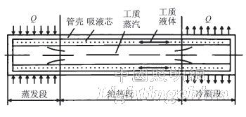
Figure 1 Schematic diagram of the heat pipe working principle
The heat pipe heat exchanger based on the heat pipe principle belongs to a surface heat exchanger in which the hot fluid and the cold fluid do not contact each other. The heat pipe heat exchanger has the remarkable features of simple structure and high heat exchange efficiency. Under the condition of transmitting the same heat, the heat consumption of the heat pipe heat exchanger is less than that of other types of heat exchangers. The pressure loss of the heat exchange fluid passing through the heat exchanger is smaller than that of the other heat exchangers, and thus the power consumption is also small. Since the cold and hot fluids exchange heat through different parts of the heat pipe heat exchanger, and the heat pipe components are independent of each other, even if a heat pipe fixed in the lamp frame fails, the perforation does not affect between the cold and hot fluids. How much isolation and heat transfer have an impact.
Taking into account the rapid thermal conductivity of the heat pipe and good environmental adaptability, Neopac applied heat pipe cooling technology to LED lamps in September 2005 [3].
2 Principle and application of semiconductor thermoelectric conversion device
In 1821, Seebeck discovered that when two different metal conductors were connected into a closed circuit, if two of their contacts were placed in two environments with different temperatures, current would be generated in the circuit. This phenomenon is known as the Seebeck effect, in which case the electromotive force that produces the current is called the thermoelectromotive force. The essence of the Seebeck effect is that the contact potential difference occurs when the two metals are in contact, and the potential difference depends on two basic factors of the electron work function and the effective electron density of the metal. For example, a cold joint of iron and copper is 1e, and a hot joint is 100e, and a thermoelectric potential of 512 mV is generated.
Figure 2 is a schematic diagram of the Seebeck effect. Let the conductors A and B have free electron densities of NA and NB, and have NA>NB. As a result of electron diffusion, conductor A loses electrons and is positively charged, and conductor B is negatively charged by electrons, forming an electric field at the contact surface. This electric field prevents the electrons from continuing to diffuse. When the dynamic equilibrium is reached, a stable potential difference, that is, the contact potential, is formed in the contact region.
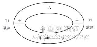
Figure 2 Scheiber effect diagram
The temperature difference of the semiconductor is most obvious and can be used as a thermoelectric conversion device. As shown in Fig. 3, if the P-type semiconductor and the N-type semiconductor are connected at the hot end, a voltage can be obtained at the cold end, and a plurality of such PNs are combined in series and one end is at a high temperature state, and the other end is at a low temperature state. Since the thermal excitation at the high temperature end is strong, the hole and electron concentrations are also higher than the low temperature end. Under the carrier concentration gradient, holes and electrons diffuse toward the low temperature end, thereby forming a potential difference at the low temperature open end [ 4].
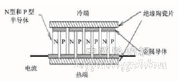
Figure 3 Schematic diagram of the actual structure of the semiconductor thermoelectric power reactor
3 LED heat dissipation and energy harvesting system
3.1 System Overview
Combined with the above heat dissipation and thermoelectric conversion technology, the energy flow of the LED lamp heat dissipation and energy recovery system proposed in this paper includes heat dissipation, thermoelectric conversion and energy storage. The system flow is shown in Figure 4. The residual heat is first transmitted to the LED plane through the inner substrate, and after two energy flow chains, the first is the process of converting the residual heat into electrical energy through the semiconductor thermoelectric device; the second is the process of rapidly transferring the thermal energy through the heat pipe technology. The controllable fan on the chain enables automatic adjustment of this energy chain.
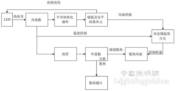
Figure 4 system flow chart
In the application, according to the seasonal changes, the first energy chain is the main one, and the second one is supplemented to realize the safe and efficient operation of the LED lights.
3.2 Structural design
The system mainly includes LED planar light source, internal and external heat dissipation substrate, heat pipe heat sink, chip type semiconductor thermoelectric conversion device, heat dissipating fin, bimetal temperature switch, cooling fan and energy storage battery. In practical applications, it can be flexibly designed according to different requirements. Figure 5 is a schematic diagram of the structure of a heat dissipation and waste heat recovery system for LED lamps.

Figure 5 Schematic diagram of an LED lamp heat dissipation and waste heat recovery system
The back surface of the LED planar light source is closely attached to the lower surface of the inner substrate, and the heat sink is closely attached to the upper surface of the inner substrate; the outer surface of each outer substrate is provided with heat dissipating fins; and between the inner side surface of each outer substrate and the outer side surface of the inner substrate a chip type thermoelectric converter, the side of the thermoelectric converter and the outer side of the inner substrate is a hot end; the side of the thermoelectric converter that is in close contact with the inner side of the outer substrate is a cold end, and the cold and hot ends of each thermoelectric converter pass through the string, and or The chip type thermoelectric converter in the structure is composed of a semiconductor thermoelectric power generation component based on the Seebeck effect; the heat sink is a heat pipe heat sink, and includes a heat dissipating fin set and a plurality of heat pipes disposed under the heat dissipating fan, and the heat pipe One end is a cold end, and the heat radiating fin group is connected; the other end of the heat pipe is a hot end, and an aluminum seat plate is attached to the upper surface of the inner substrate, and the aluminum seat plate is provided with a bimetal temperature switch, and the input end thereof is electrically The energy storage conversion unit is connected; the output end of the bimetal temperature switch is electrically connected to the heat dissipation fan, and the inner and outer substrates are made of a metal copper plate which is easy to conduct heat; the heat dissipation fins are formed by connecting a plurality of thin aluminum sheets in an inverted U shape.
3.3 Working process
The LED planar light source is composed of many PN junction particles. When it emits light, only 20%~30% of the energy is converted into light, and the remaining 70%~80% of the energy is converted into heat. If the residual heat is not emitted, it will not only seriously affect The life of the lamp, but also there are security risks. In order to ensure that the LED lamp operates in a safe temperature range, referring to the system flow chart of FIG. 4, first, the heat concentrated on the LED planar light source is uniformly distributed on the inner substrate by direct heat conduction. Then consider the waste heat generated by recycling and recycling from the aspect of energy saving, that is, using the semiconductor thermoelectric converter to convert the heat into electric energy and temporarily store and convert the energy through the energy storage conversion unit to output part of the LED lighting power and supply the cooling fan according to the specific environment. . Heat dissipating fins are added on the outer side of the outer substrate of the cold junction of the semiconductor thermoelectric converter for auxiliary heat dissipation to increase the temperature difference between the hot and cold ends of the semiconductor thermoelectric converter and improve the thermoelectric conversion efficiency.
Considering the difference between the thermoelectric efficiency of the semiconductor and the external temperature of the four seasons, the heat pipe radiator and the cooling fan with the built-in bimetal temperature switch constitute a residual heat evacuation module. The heat pipe heat sink transfers the excess heat of the inner substrate to the upper inverted U-shaped heat radiating fin group through the heat pipe technology, and then combines the fan to dissipate heat.
The bimetal temperature switch uses a temperature value as a temperature component that controls ONPOFF. The principle is to use the characteristics of the metal to be bent after being heated to cause the internal switch to act. The manual reset and automatic reset type, the system uses the automatic reset type. Since the thermoelectric efficiency of the existing semiconductor thermoelectric converter is not very high, if the outdoor temperature is high in summer, it will inevitably cause heat to accumulate around the substrate and cannot be dissipated. We use a bimetal temperature switch to control the cooling fan to solve. A typical application process is as follows: a bimetal temperature switch has a closing temperature of 50e and the other is 55e. According to the LED power size, the heat dissipating fin size and the fan power are specifically set. When the temperature of the LED planar light source reaches 50e, that is, when the temperature sensed at the switch reaches 50e, one switch is closed, and the fan is controlled to operate at half speed. This state is what happens when the ambient temperature around the spring and autumn lights reaches about 30e. When the temperature of the LED planar light source reaches 55e, both switches are closed, thereby controlling the fan to run at full speed and dissipating the accumulated residual heat as quickly as possible. This is what happens when the ambient temperature around the summer lights reaches around 40e. In the winter or spring and autumn nights, the fan may not be turned on. The heat sink fin group can completely make the LED plane light source temperature lower than 50e, and the converted electric energy is all used for auxiliary lighting. Since the switch used is an automatic reset type, the opening or closing of the fan is completely determined by the temperature of the LED planar light source, realizing true automatic control.
In general, the system guarantees the maximum possible waste heat recovery utilization rate, and according to the actual situation, the excess heat that may harm the LED light source in the process of thermoelectric conversion is dissipated in time, achieving the purpose of safety, high efficiency and energy saving.
4 Conclusion
Compared with the existing lighting device, the system has the following four advantages: First, the LED planar light source is packaged into a new type of lighting device together with the heat dissipation and waste heat utilization device to reduce the volume; secondly, the heat dissipation of the high power LED light source is broken. The bottleneck further expands the application range of LED lamps; thirdly, the cooling fan is automatically controlled by the bimetal temperature switch, which is more precise and efficient. At the same time, the cooling fan does not need additional power supply, and the heat dissipation cost is greatly reduced. Fourthly, it is also the biggest feature of the system: the use of semiconductor thermoelectric conversion to recover waste heat, and obtains the technical effect of high efficiency and energy saving. The thermoelectric conversion efficiency of the existing semiconductor thermoelectric converter on the market is generally 30%. For example, 60% of the heat output of the LED is sent to the semiconductor thermoelectric converter. According to the calculation, according to the electricity consumption of the country in 2006, the electricity consumption is about 210 billion kilowatts. With this lighting device, it can convert and generate 37.8 billion kilowatts of electricity.
Edit: Cedar
As a Professional manufacturer of stage lights, our products base on High Quanlity Standard and competitive prices.
Moving head Beam Lights, wash zoom lights, LED Par Lights, COB matrix light, laser lights and fog machines, professional solution for decerating stage effects.
Stage lighting series products can be used in various large and small concerts, bars, restaurants, clubs, etc. Program them to make good effects for any stage by using DMX Controller. We also provide free solution for your to fit well to the plan.

Stage Light,Led Stage Lights,Stage Lighting,Stage Lighting Systems
Guangzhou Cheng Wen Photoelectric Technology Co., Ltd. , https://www.ledscreencw.com