AC-DC power module application troubleshooting
Switching power supplies are favored by many product designers due to their multiple advantages such as high integration, high reliability, and simplified design. However, their easy-to-handle and simple operation make many product designers have some problems in use, so this article starts from From these perspectives, through analyzing the common use problems of switching power supply and how to troubleshoot, we will elaborate in detail, hoping to be helpful to our daily product design.
1. After the input voltage is connected, the module has no output or is directly damaged?
Due to improper power supply peripheral components, damaged components, harsh electromagnetic environment or misoperation, etc., the module may have no output voltage or be directly damaged after power-on.
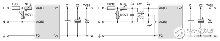
Figure 1 The peripheral circuit usually connected to the power supply module
(1) The output pin is soldered incorrectly or the customer PCB residual tin slag causes the output to be short-circuited, making the module in the short-circuit protection state. It is recommended to solder the pins or clean the PCB correctly according to the module silkscreen. After the short-circuit condition is eliminated, the power can be restored to normal.
(2) The external fuse FUSE of the input is damaged. Check whether there is a short circuit in the input front circuit of the module. Secondly, check whether the fuse size is too small. It is recommended to select the fuse according to the recommended specifications in the specification.
(3) The customer's operating voltage environment is unstable, and there is a possibility that the input voltage is too large, which will cause the module to be damaged instantly when it is started. It is recommended to supply power to the module within the range required by the specification.
(4) At the moment when the module is started, there is a large inrush current, which causes the module to be damaged when it is started directly. It is recommended to add a surge suppression circuit at the front of the module according to the protection circuit recommended in the specification.
2. Why is the output voltage of the module at start-up unstable or low?
(1) It is usually recommended to add a certain filter capacitor to the output terminal of the power module, but during use, due to insufficient understanding and other reasons, an excessive output filter capacitor is used.

Figure 2 Excessive capacitive load
As shown in the circuit (a) in Figure 2, a 3W module uses a 2000uF capacitor for its output. According to the product manual, it is suggested that the maximum output capacitance of the module is 800uF. Excessive output capacitance may cause poor startup or low output voltage. It is recommended that the capacitance of the external output capacitor of the module is not greater than the maximum capacitive load specified in the product manual.
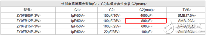
Figure 3 Typical and maximum capacitive load
(2) When using the module, the customer did not accurately estimate the required power supply module power, making the module in an overload start or overload working state.
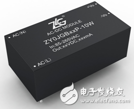
Figure 4 ZY0JGBxxP-10W series power module
As shown in the ZY0JGBxxP-10W series power module in Figure 4, the rated power of the module is 10W, that is, the power range of the module cannot exceed 10W, otherwise it may cause the module to start poorly or the output voltage is low. It is recommended to switch to a higher-power power supply module or reduce the load.
3. The ripple noise of the module exceeds the maximum value marked in the product manual?
The output of the switching power supply is not a pure DC voltage. There are some AC components in it, namely ripple and noise. There are two reasons for noise products, one is the switching power supply itself, and the other is the external electromagnetic field interference (EMI), which can be input to the switching power supply through radiation or power lines. Due to the wide variety of switching power supplies, each power supply manufacturer has its own measurement standards. Therefore, inconsistent bandwidth selection of the oscilloscope or different test methods may lead to different measured results. It is recommended that the bandwidth of the oscilloscope should be 20MHz, and then the measurement should be carried out according to the method required in Figure 5.
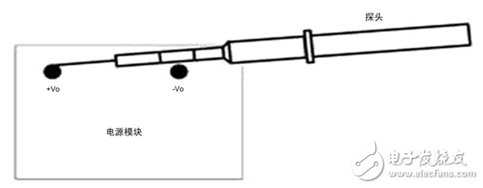
Figure 5 Noise test standards
4. The module does not work normally or is easily damaged under severe environmental temperature?
The power supply is a kind of electrical energy conversion equipment. During the conversion process, it needs to consume some electrical energy, and the electrical energy is converted into heat and released. The stability and aging speed of electronic components are closely related to the ambient temperature. Therefore, improper use will cause the module to not work normally or be damaged after a period of work.
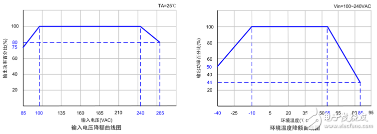
Figure 6 Derating curve
(1) a. The temperature rise is too high, the output voltage of the module oscillates intermittently, and the phenomenon of over-temperature protection occurs.
b. The output ripple increases or the power supply is bulging.
C. The module is damaged.
It is recommended that when the ambient temperature is too high, strictly follow the derating curve in the product manual, or use a power supply module with higher power.
(2) It can not start normally or there is a spike in the start under low temperature.
It is recommended that when the ambient temperature is low, strictly follow the derating curve in the product manual.
5. Are CE marked products installed in other systems and must meet EMC requirements?
Not necessarily. Generally, the location of the power supply in the system, the arrangement of the wire group, and the system grounding design will cause some degree of influence. The same power supply often has different results in different use environments or applications. If the module does not meet the EMC requirements or the module and the customer’s system interfere with each other, it is recommended to appropriately adjust the distance between the module and the sensitive device, take shielding measures, and connect the recommended EMC protection circuit in accordance with the data manual.
(1) a. The temperature rise is too high, the output voltage of the module oscillates intermittently, and the phenomenon of over-temperature protection occurs.
b. The output ripple is increased or the power supply is bulging.
C. The module is damaged.
It is recommended that when the ambient temperature is too high, strictly follow the derating curve in the product manual, or use a power supply module with higher power.
(2) It can not start normally or there is a spike in start under low temperature.
It is recommended that when the ambient temperature is low, strictly follow the derating curve in the product manual.

Figure 7 Zhiyuan Power Module
6. How to extend the service life of AC-DC switching power supply?
It is generally believed that as the ambient temperature increases by 10°C, the life of electrolytic capacitors is reduced by half, and electrolytic capacitors are indispensable components of AC-DC switching power supplies, so it can be said that the life of electrolytic capacitors largely determines the service life of switching power supplies. It is recommended to use a module with 30% more output rated power. For example, if the system requires a 15W power supply, it is recommended to choose a module with a rated power output of not less than 20W (such as ZY0JGBxxD-20W), and so on can effectively extend the service life of the power supply.
Scope of supply
Rating: Up to 200MVA
Voltage:Valve side voltage up to 1000VDC, Grid side voltage up to 220KV
Double star and double bridge
Applications:
The rectifier transformers are mainly used in the electrolysis processes for production of different kind of metals, such as aluminum electrolyzing, magnesium electrolyzing, copper electrolyzing, zinc electrolyzing and other more applications. The largest installed rectifier transformers are always for aluminum electrolysis with some transformer/rectifier combined units in parallel operation to get the required DC current.
Design:
The rectification method is normally known as double star or double bridge. Double star systems use an interphase transformer (IPT) and are usually applied as 6 or 12pulse units where high currents are required with very low nominal voltages. Double bridge system is applied as 6, 12, 24, 48 or 60pulse systems, as required to suit the harmonic mitigation and process stability requirements.
Duty
Electrolysis is normally a continuous process, but with a constant high loading and current harmonics.
Why SCOTECH
Long history- Focus on transformer manufacturing since 1934.
Technical support – 134 engineers stand by for you 24/7.
Manufacturing-advanced production and testing equipment, strict QA system.
Perfect service-The complete customer service package (from quotation to energization)
Rectifier Transformer,Bridge Rectifier Transformer,12 Pulse Rectifier Transformer,High Voltage Rectifier Transformer
Jiangshan Scotech Electrical Co.,Ltd , https://www.scotech.com