Abstract As a new energy vehicle, electric vehicles have good social benefits and are environmentally friendly. The electric vehicle charging station is connected to the photovoltaic grid-connected power generation device to access the cleaner electric energy. In the paper, the Z-source inverter is used in the photovoltaic access-type power generation device, which has more advantages than the traditional inverter, and is simulated by Saber. The software simulation of the model shows that the device is reasonable and feasible.
Keywords Z source inverter; photovoltaic power generation; electric vehicle charging station
Under the dual challenges of energy crisis and climate warming, electric vehicles can save energy, reduce pollution, improve energy structure and grid load, and become an important way to develop low-carbon economy and implement energy-saving and emission-reduction policies. As a new energy vehicle, electric vehicles are conducive to advocating green, energy-saving and environmental protection concepts, promoting the transformation of China's transportation development model, and have broad market prospects and environmental benefits.
The construction and promotion of electric vehicle charging stations in China is a major measure to implement the national energy strategy, develop a low-carbon economy, respond to energy-saving and emission reduction policies, participate in building a resource-conserving and environment-friendly society, and is also an important part of building a strong smart grid in China. . If the electric vehicle smart charging station is connected to the distributed solar photovoltaic system, the system can be connected to clean energy, so that the clean electric energy can be integrated into more parts of the power system. In this paper, a photovoltaic access power generation device for electric vehicle charging station is designed, which uses Z source inverter instead of traditional inverter to realize energy conversion.
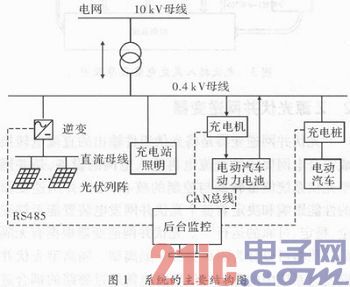
1 The main structural system of the system is mainly composed of solar cell modules, DC combiner boxes, grid-connected inverters, AC and DC distribution boxes, various loads in the station and background monitoring systems. As shown in Fig. 1, the device converts solar energy into direct current electric energy through a photovoltaic array, and then merges the direct current electric energy into an alternating current current conforming to the phase and frequency of the alternating current grid through the grid-connected inverter through the DC bus. A low-voltage grid that can be used to power lighting and other light-load equipment in electric vehicle charging stations. When daylight and temperature requirements are met during the day, the device can meet the output power requirements, and automatically connect to the grid for power generation. When the solar illumination is insufficient, the power output is insufficient. The device automatically removes the off-grid and the grid supplies power to the station separately. The DC output of the PV array, the input and output parameters of the grid-connected inverter, and the parameters of the station's charging and replacing equipment and energy storage equipment are monitored by the background monitoring system.
This article refers to the address: http://
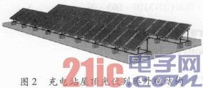
In addition, the electric vehicle charging station will become part of the distribution network. The electric vehicle's power battery can also be used as an energy storage system. It will also be one of the more promising energy storage methods. It has the ability to cut peaks and fill the grid, load compensation, and improve The role of power quality, and can stabilize the new energy output and optimize the grid-connected performance of new energy generation. The solar photovoltaic module of the system is installed on the roof of the completed charging and replacing workshop in the electric vehicle charging station through the fixed bracket at a mounting inclination angle of 35°, and the grid-connected photovoltaic inverter is used to realize centralized centralized grid-connected power generation. The appearance structure is shown in Figure 2.
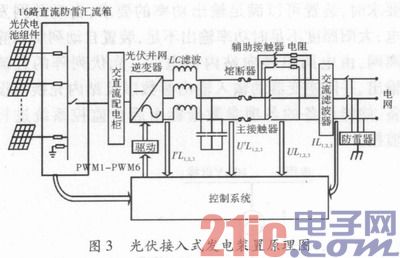
The photovoltaic module is 185 W. The solar cell module has an operating voltage of 36.71 V and a total of 272 components. The actual peak power of the entire power generation system is 50.32 kW. Each of the 17 battery modules is composed in series, and 272 battery components total 16 channels. After the battery strings are connected, the DC lightning protection combiner boxes are merged. The DC lightning protection combiner box has 16 protection control and current monitoring devices. Each positive and negative poles are equipped with high voltage DC circuit breakers. The withstand voltage can reach DC 1 kV. Current monitoring can monitor the current of each battery string. . The DC bus voltage is 624.07 V, and the output current after DC sink is 80.63 A. As shown in FIG. 3, after the convergence, the grid-connected inverter is converted into a three-phase alternating current through LC filtering and the alternating lightning protection power distribution cabinet is incorporated into the low-voltage power grid of the charging station.
2 Z-source photovoltaic grid-connected inverter Photovoltaic grid-connected inverter is a device that converts the direct current output of photovoltaic modules into AC power and then enters the grid. It is the core of energy conversion and control of grid-connected photovoltaic systems. The performance impact of the grid inverter determines whether the entire photovoltaic grid-connected power generation unit can operate safely, stably and reliably. Photovoltaic grid-connected inverters can be classified into isolated and non-isolated types depending on the presence or absence of isolation transformers. The isolation transformer in the isolated photovoltaic grid-connected power generation system transfers the electric energy through the coupling of the magnetic circuit, which will cause a certain power loss during the transmission process. Under normal circumstances, the energy loss caused by the general small-capacity transformer can reach 5% or even higher. If an isolation transformer is used, the quality and volume of the system will increase, the investment will increase, and the structure will be more complicated. Therefore, the use of a non-isolated photovoltaic grid-connected inverter structure that eliminates bulky power frequency transformers or complex high-frequency transformers is one of the effective means to improve the efficiency of photovoltaic grid-connected energy conversion.
The conventional voltage source grid-connected inverter topology has the following problems: To prevent short-circuiting of the DC-side capacitor caused by the through-through, the two tubes of the upper and lower arms of the inverter bridge need to be connected to the dead time; Where the voltage is higher than the grid voltage amplitude; the DC side support capacitor value should be designed to be large enough to suppress DC voltage ripple.
In view of the shortcomings of the conventional inverter topology, the device adopts the Z-source network-based inverter topology proposed by Professor Peng Fangzheng. Compared with the conventional voltage source inverter, this new voltage source inverter can allow the through-pass. The state exists, that is, the two semiconductor tubes of the upper and lower arms of the same phase are allowed to be simultaneously turned on, thereby protecting the entire inverter circuit, and the addition of the through time makes the circuit have a boost function, and the Z source network is added to make the load of the circuit. It can be either capacitive or emotional.
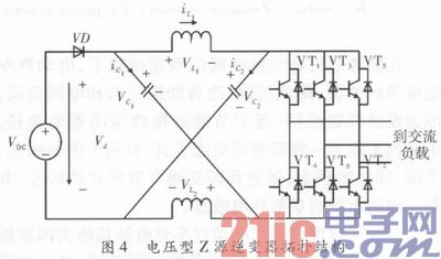
The general structure of the voltage-type Z-source inverter is shown in Figure 4. When the upper and lower bridge arms of the same phase are simultaneously turned on, the inverter works in the through state. At this time, the inverter bridge is equivalent to a short circuit, equivalent to a zero value. Current source; under normal circumstances, the inverter works in a non-through state, and the inverter bridge is equivalent to a constant current source. The peak value of the DC voltage output by the Z source network is ![]()
Where B is the boosting factor. When the through-time of the circuit changes, the straight-through duty ratio d0 changes, and finally the boosting factor B changes, which acts to regulate the voltage.
The peak value of the inverter AC output phase voltage is ![]()
Where M is the modulation factor of the inverter. When M is increased, the through-duty ratio is reduced. It can be seen from equation (1) that B will decrease, and if M decreases, B will increase. By properly adjusting the values ​​of M and B, the output voltage can be adjusted, and the buck-boost voltage regulation function can be realized more flexibly. In addition, the inverter of the device also has a maximum power point tracking function to ensure that it can automatically track and output at maximum power when the temperature and sunshine changes are large. When the grid side is powered off, it can automatically detect and stop the system unit to avoid the island operation.
3 Saber simulation and result analysis According to the actual parameters of the DC voltage and current output of the photovoltaic array of the device and the topology structure of the voltage-type Z-source inverter, the simulation circuit model is built. In the main circuit, the inverter bridge adopts the fully-controlled device IGBT, Z. The capacitor inductance in the source network is calculated by using the reference value L1=L2=30 mH, the capacitor C1=C2=25μF, the output is LC filtered, the output filter capacitor C3=C4=C5=2.5μF, and the filter inductor is L3=L4=L5 =18 mH. Using Saber software to simulate and analyze the experimental circuit, the main circuit and the control circuit adopt modular form, which is easy to control and easy to implement.
The inverter control circuit and the experimental simulation circuit of the photovoltaic grid-connected power generation device adopt simple boost control. This method still belongs to the PWM control, and compares the sine wave with the triangular wave. The difference is that the improvement is based on the traditional PWM control. . Two DC voltages vp and vn are added to the control, the value of which should be greater than or equal to the peak value of the three-phase sinusoidal AC voltage, and vp and vn are used as reference voltages to adjust the through-duty ratio, as shown in FIG.
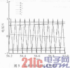
The Z-source inverter maintains six active states, the same as traditional sinusoidal PWM modulation. As can be seen from equation (1), the maximum through-duty of this control mode does not exceed (1-M), so when the modulation factor is 1, the through-duty is 0, and the voltage gain is G=MB.
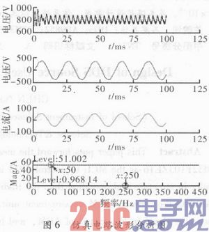
In Figure 6, the waveforms from top to bottom are Z source network port output voltage, inverter AC side output phase current, inverter AC side output phase voltage and AC side output phase current harmonic analysis, DC input voltage in the simulation circuit. For 624 V, the modulation factor M is 0.9, the through-duty ratio is 0.11, the reference voltage is vp=0.78 V, vn=-0.78 V, and the signal wave frequency is 50 Hz. It can be seen that when the input DC voltage is 624 V, the output AC phase voltage peak can reach nearly 380 V, and the frequency can be realized as 50 Hz. From the simulation results, the harmonic analysis, the 5th and 7th harmonics are slightly obvious, Calculate, the 5th harmonic current content of the output phase current of the AC side is HR15=1.9%, the 7th harmonic current content rate HR17=1.5%, the current harmonic total distortion rate THDi=3.3%, harmonic The wave pollution is small, and the output waveform is relatively smooth, which is in line with the grid connection requirements in the literature.
4 Conclusion paper electric car charging stations access type photovoltaic power generation apparatus using Z-source inverter, compared with the conventional inverter has certain advantages, simulation results show that after the device is reasonable and feasible, the power system during the day to the station with which the PV Load power supply, when the night and sunshine are insufficient, the grid is separately powered, which can contribute more clean energy to the grid, which has high energy conservation and environmental protection significance.
Desktop Type Power Adapter, small size switch with12VDC,12W,24W,36W,60W
Features:
Wide input range: 100-240V, 50/60Hz.
Full current,all using brand new capacitors
Glass fiber board (FR-4)
Special shield housing design for cooling.
Plastic housing use ultrasonic process, it is No need any screw.
Protections:short circuit, over current, overload.
Customized Ac Plug, EU,UK,USA,AU Plug is available
4 times aging test
100% Enough Power,
High efficiency 85%.
3 years warranty
Product application:
Application to CCTV, Access control,Alarm System.
Desktop Type Power Adapter
Desktop Type Power Adapter,Power Supply Plug Type, Power Adaptor,Power Inverter
Guangdong Steady Technology Co.LTD , https://www.steadysmps.com