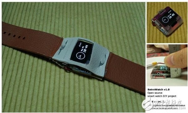
When it comes to wearable devices, the first thing we think of is the smart watch. Buying a stylish smart watch is certainly good, but as a maker, you can also choose to do it yourself!
I named this DIY smart watch as Retro Watch. The whole project is based on Android and Arduino development board. All the hardware and software design of the project is open source. You can download the source code or contribute your strength on Github. It's also worth mentioning that Retro Watch already supports u8glib, which allows you to choose any screen you want to use (including OLED), and the RAM used by the screen can be reduced.
The first step: system structure design
As shown above, the structure of Retro Watch is relatively simple: the hardware platform is based on Arduino, which has only one control button. In addition, I also developed an Android-based application that allows the watch to connect via Bluetooth and Android devices so that we can view RSS feeds and system notifications on Android devices via Retro Watch.
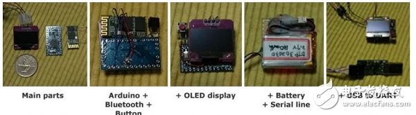
Step 2: Component Preparation
Because we have to do a smart watch, ensuring the compactness of each component is also one of the keys.
Arduino microcontroller
I chose the smallest Arduino, Pro Mini, which is a lightweight version of Uno R3. There is no USB interface chip on it, so you need to prepare a USB to UART module. The Arduino has two versions with different operating voltages (3.3v/5v). I chose the 3.3V version because the Bluetooth module and display support 3.3V, and the 3.7V LiPo battery can be used normally.
The 3.3V version of the Arduino operates at 8MHz, and the 5V version operates at 16MHz, but 8MHz is sufficient.
The core processing device of the Arduino Pro Mini is the ATmega328 microcontroller, which has a RAM of 2KB. The Arduino version of ATmega128 with only 1KB of RAM is not enough.
Bluetooth
The HC~06 Bluetooth module is more common. One of them has an interface board that contains a reset button and an LED, but the volume is relatively large. In view of the fact that the interface board does not make much sense to the project, it also increases the cost, so the HC~06 without the interface board is selected here.
Display
We need a display that is small enough and low enough. I finally chose Adafruit's 0.96-inch 128×64 OLED display, which supports I2C, SPI, and can be easily connected to the Arduino. I chose the I2C and SSD1306 driver chips here.
battery
My choice is a 3.7V LiPo battery with a capacity of 140mAh. General use can last for 7 hours. Again, choosing the size of the battery is important.
other
In addition to components such as wires, a 10 kΩ resistor (for button connections) is required.
The third step: assembly
The hardware structure connection diagram of the whole system is as follows:
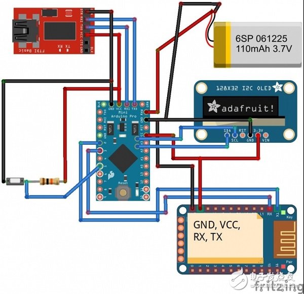
Bluetooth connection Arduino:
·VCC ~ 3.3V
·GND ~ GND
·TX ~ D2
·RX ~ D3
OLED connection Arduino:
·GND ~ GND
·VCC ~ VCC
·SDA ~ A4 (analog pin 4)
·SCL ~ A5 (analog pin 5)
If you are using the SPI interface, you can refer to the Adafruit tutorial as follows:
· D1 : MOSI ~ Arduino D11 (MOSI)
·D2 : MISO ~ Arduino D12 (MISO) (optional)
·D0 : CLK ~ Arduino D13 (SCK)
·DC : DC (data command) ~ Arduino D8 (or other)
·CS : CS (Chip Select) ~ Arduino D10 (SS)
·RES : RESET ~ Arduino D9 (or other)
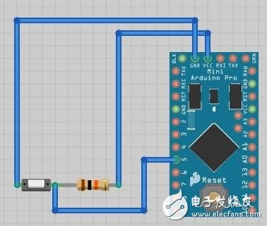
Button:
The connection is shown in the figure. Note that a 10 kΩ resistor is used here.
Battery connection Arduino:
·Positive ~ RAW
·Negative ~ GND
USB to UART module to connect Arduino:
·3.3V ~ VCC
·TXD ~ RXD
·RXD ~ TXD
·GND ~ GND
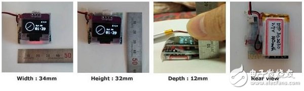
The installation dimensions are as follows:
Step 4: Compile the Arduino code and upload it
The already completed Arduino project can be downloaded on GitHub. Don't rush to compile after downloading, you need to configure the development environment first.
Install the graphics driver:
First you need to install the graphics processing library Adafruit_SSD1306 and Adafruit-GFX-Library so that you can display images on the OLED. (In some development environments, the Adafruit library will conflict with the Robot_xxx library; if this happens, back up the Robot_xxx library and remove it from the library folder.)
Warning: If you are using an OLED with SH1106 driver, download the Adafruit_SH1106 driver on GitHub.
In addition, this project also supports u8glib, you can download the version that supports Arduino on its official homepage.
Copy the bitmap image header file:
Copy the bitmap.h file from the RetroWatchArduino folder to the path /Arduino installation folder /Arduino/hardware/libraries/RetroWatch. If you don't have such a path, you can create it yourself.
Modify the source code:
Open the Arduino IDE and load RetroWtchArduino.ino. If you use a different pin than this one, you need to modify the pin definition:
SoftwareSerial BTSerial(9, 8); //Bluetooth TX, RX connection pin
Int buttonPin = 5; // button pin
Display.begin(SSD1306_SWITCHCAPVCC, 0x3C); // OLED I2C address, replace Ox3D with your address
If you are using u8glib, load the RetroWatchArduino_u8glib.ino file and note the following code:
U8GLIB_SSD1306_128X64 u8g(U8G_I2C_OPT_NONE|U8G_I2C_OPT_DEV_0); //Modify according to the display you selected
SoftwareSerialBTSerial(2,3); // Bluetooth TX, RX connection pin
Int buttonPin = 5; // button pin
If you are using Adafruit's graphics library and have used the Reset pin of the OLED, then connect the OLED Reset to the D8 pin of the Arduino, but you can also customize it:
#define OLED_RESET 8
Adafruit_SSD1306 display(OLED_RESET);
Compile and upload:
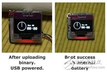
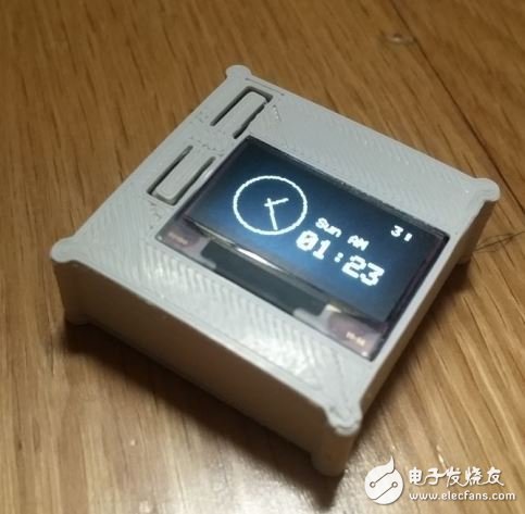
After the above steps are completed, compile and upload. After successful, the RetroWatch Arduino Logo and Adafruit Logo will be displayed on the display. After the Logo, the screen will display 00:00, as shown below:
Step 5: Android software and its source code
Because Android 4.3 and later support reading notifications from apps, make sure your Android device is installed with Android 4.3 or newer. But if you're using a version lower than 4.3, you can use another castrated app: you can receive notifications through your smart watch, but you can't read the content. Application source code can be viewed on GitHub or directly from the Google Play Store (RetroWatch or RetroWatch LE for lower versions).
After the Android software is installed, check if the system has granted permission to read the notification.
Next, open the phone Bluetooth and pair the Android phone with the Arduino's Bluetooth. Then select the connected Arduino in the RetroWatch software, and the message “Connected†on the interface indicates that the connection is successful.
Click on the menu and select Data transfer to Watch, then the device will use Bluetooth to transfer time and information to the smart watch.
Because the performance of the watch hardware is limited, many functions need to be implemented through the Android application, and the main function of the watch itself is display. In the Android app, you can set the type of pushable message (only supports English character display) and status notification (mobile phone battery power and signal strength, etc.), or you can push RSS subscribed to the app (you can subscribe to weather RSS for use in The weather is shown on the watch). The update is synchronized every 30 minutes.
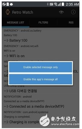
In addition, the app also provides 65 different display icons, you can define the settings yourself.
Step 6: Introduction to the watch function
Once you're ready, explore our smartwatch. The system of smart watches works in the following modes:
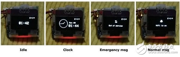
Start display: Display Logo, watch starts.
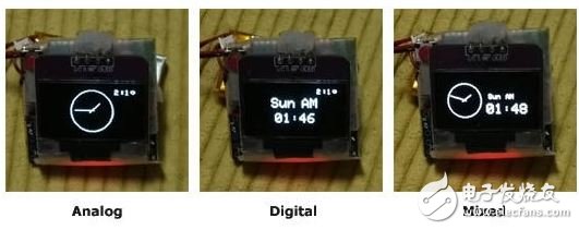
Clock display: Shows the time on the Android phone connected to it. In addition, the display of time can be modified, and currently provides three modes of analog display, digital display and mixed display. If you click the button, the watch enters the emergency message display mode. If there is no data update and operation within 10 minutes, the display interface will switch to the standby interface.
Emergency message display: When the user clicks the button or has a new emergency message input, the watch enters this mode. The user can click the button again to view the next message, and the watch will automatically display the next message if it is not operated for 10 seconds. After the information display is completed, the watch switches to the normal information display. Because RAM is only 2KB, it is very small. Therefore, the smart watch stores up to 3 emergency messages, and when more than 3, the oldest information is automatically deleted.
General information display: After the emergency information display is completed, the watch will continue to display the general information. Click the button or 5 seconds to display the next message. After the information display is completed, the watch switches back to the clock display. A maximum of 7 general information is stored.
Standby display: If there is no data update and operation within 10 minutes, the display interface will switch to the standby interface. In this mode, the watch interface only displays the indicator (selectable in the Android app) and the hh:mm mode, and its power consumption is also reduced. When the button is clicked in standby mode or a new message is received, the watch enters the clock display mode.
Step 7: External structure production
You can make a simple package by hand:
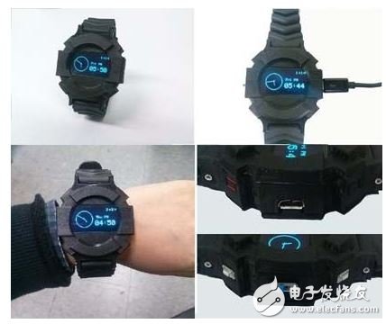
You can also download 3D files to make a cool watch:
Of course, you can choose not to wear a watch, and it is good to be a desktop reminder:
Powered Subwoofer,Aluminum Cone Woofer,Indoor Active Subwoofer,Home Theater Subwoofer
The ASI Audio Technology Co., Ltd , https://www.asi-sound.com