Diode and Zener Diode-Based Voltage Divider Circuits
Sometimes, we need to generate several milliamps of current from two or more low-voltage power supplies or DC sources. In such cases, the power management doesn't have to be extremely precise. One effective way to achieve this is by using voltage dividers based on diodes, Zener diodes, or shunt regulators. These circuits are simple, cost-effective, and suitable for applications where high precision isn't required.
Modern Zener diodes come in a wide range of power ratings, typically between 0.3W and 1.3W, with a reference voltage tolerance of ±2% or better. This makes them ideal for use in basic voltage divider configurations. Figure 2 illustrates three different examples of such circuits.
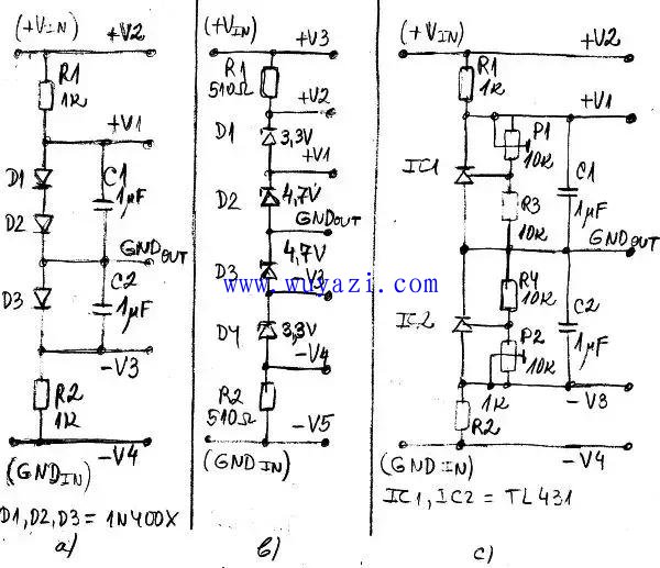
Figure 2: Voltage divider using diodes and Zener diodes. a) A voltage divider using a standard diode; b) A voltage divider using a Zener diode; c) A voltage divider using two shunt regulators (TL431).
In Figure 2a, a simple voltage divider is constructed using regular diodes. By connecting multiple diodes or even LEDs in series, you can create a shunt regulator that provides a stable output voltage. In this example, two diodes D1 and D2 produce a positive voltage +V1, while another diode D3 generates a negative voltage -V3. The ground point (GNDout) can be placed anywhere between the diodes, offering flexibility in design.
Figure 2b shows a similar approach but uses Zener diodes instead. These diodes can be connected in series to provide both positive and negative output voltages. For instance, D1 and D2 produce +V1 and +V2, while D3 and D4 generate -V3 and -V4. The ground point (GNDout) is placed between D2 and D3 in this case. Zener diodes can be of the same or different types, depending on the desired voltage levels.
Instead of using standard diodes or Zener diodes, you can also employ an adjustable shunt regulator like the TL431. This offers greater flexibility, as the output voltage can be fine-tuned using resistors, trimmer potentiometers, or other components.
Figure 2c demonstrates a voltage divider using two TL431 or LM341 shunt regulators. In this configuration, one regulator produces a positive output voltage +V1, while the other generates a negative voltage -V3. The output voltages can be adjusted using trimmers P1 and P2, respectively.
You can connect any number of shunt regulators in series, just like in Figures 2a and 2b. In fact, these regulators function similarly to adjustable Zener diodes, making them a powerful tool in low-power voltage regulation applications. Whether you're working with simple diodes, Zener diodes, or advanced shunt regulators, each method has its own advantages and can be chosen based on the specific requirements of your circuit.
Outdoor Cable,Outdoor Power Cable,Outdoor Power Cord,Outside Cable
Huizhou Fibercan Industrial Co.Ltd , https://www.fibercan-network.com