A relay is an electronic control device that consists of a control system (input circuit) and a controlled system (output circuit). It's commonly used in automatic control circuits, acting as a switch that uses a small current to control a larger one. This makes it ideal for tasks like automatic adjustment, safety protection, and signal conversion within a circuit. Most relays are electromagnets with an armature that can either close or open one or more sets of contacts. When current flows through the coil, the electromagnetic field pulls the armature toward the core, changing the contact state. Relays come in various types, including electromagnetic, thermal reed, and solid-state relays. The ones on the enhanced PIC experiment board are shown in Figure 1.
Electromagnetic relays typically consist of a core, a coil, an armature, and a contact spring. When voltage is applied to the coil, current flows, creating an electromagnetic field that attracts the armature, causing the moving contact to connect with the stationary contact (normally open). When the coil is de-energized, the magnetic field disappears, and the spring returns the armature to its original position, allowing the normally closed contact to make contact. To identify "normally open" and "normally closed" contacts: a normally open contact is open when the coil is not energized, while a normally closed contact is closed under the same condition.
Thermal reed relays are a modern type of temperature-sensitive switch. They use temperature-sensitive magnetic materials to detect and regulate temperature. These relays include a temperature-sensitive magnetic ring, a permanent magnet ring, a reed switch, and other components. Unlike traditional relays, they don’t require a coil. Instead, the permanent magnet drives the switching action, and whether it does so depends on the temperature characteristics of the sensitive ring.
Solid-state relays are four-terminal devices where two terminals serve as input and the other two as output. They provide electrical isolation between the input and output, making them ideal for applications requiring high reliability and long life. Solid-state relays can be categorized by load type (AC or DC), switch type (normally open or normally closed), and isolation method (hybrid, transformer, or opto-isolated). Opto-isolation is the most common type due to its excellent noise immunity and safety.
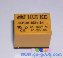
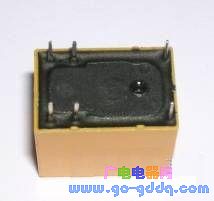
Figure 1: Relay Physical Map
Solid-state relays can be classified into AC and DC types based on the power supply type. They can also be divided into normally open and normally closed types depending on their switching behavior. In terms of isolation, they fall into hybrid, transformer-isolated, and optically isolated categories, with opto-isolation being the most widely used. For demonstration purposes, we’ll focus on the electromagnetic relay in this explanation.
Relay Control Circuit
In microcontroller systems, relays are often driven using a transistor. A typical drive circuit is shown in Figure 2:
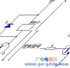
Figure 2 (a) | Figure 2 (b)
Figure 2: General Relay Drive Circuit
In a relay circuit, a diode is usually placed across the coil to suppress back EMF generated when the coil is turned off, preventing electrical interference. In the diagram, AB represents a normally open contact, and AC is a normally closed contact. In Figure (a), when the control signal is high, the normally open contact closes (AB turns on), and when the signal is low, the normally closed contact closes (AC turns on). In Figure (b), the control signal polarity is reversed. This circuit is used on the test board provided for experimentation.
65 Inch Education Interactive Board
65 Inch Education Interactive Board,Touch Integrated Machine,Interactive Smart Board Flat Panel,Multi Function Smart Conference Tablet
Jiangsu Qilong Electronic Technology Co., Ltd. , https://www.qilongtouch.com