The time delay relay is a type of relay that utilizes the pulse delay principle to achieve delayed on-off functionality. It is commonly used in relay protection and automation circuits as a timing component for delayed return after an AC instantaneous power failure.
### First, the Working Principle of Time Delay Relay – Classification
Common types of time delay relays include air-damping, electronic, and clock-type:
1. **Air-Damping Type**: This type uses an airbag that deflates through a small hole after being activated by an electromagnet, thereby delaying the command execution.
2. **Electronic Type**: This relay uses an electronic circuit to delay the execution of the command.
3. **Clock-Type**: It uses the escapement mechanism of a clock to control the release of a spring-like mechanism, offering high precision.
### Second, the Working Principle of Time Delay Relay – Circuit Diagram
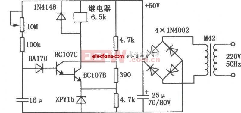
#### 1. Transistor Relay Delay Circuit
Figure 1 shows a transistor-based relay delay circuit. When the power is first turned on, the voltage across the 16μF capacitor is zero, so both transistors are off, and the relay does not operate. As the capacitor charges, after a certain period, the voltage reaches a high level, turning both transistors on, which causes the relay to pull in with a delay. The delay can be up to 60 seconds, and it can be adjusted using a 10MΩ resistor.
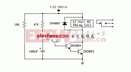
#### 2. Power-On Delay Relay Circuit
This circuit uses the base-emitter breakdown voltage of a bipolar transistor. A 2N3904 transistor is connected in reverse at the emitter-base junction, acting as an 8-volt Zener diode. This creates a higher turn-on voltage for a Darlington pair. Most bipolar transistors can be used, but the Zener voltage will likely be between 6 to 9 volts depending on the transistor. With a 47K resistor and a 100μF capacitor, the delay is approximately 7 seconds. Reducing R or C values shortens the delay, while increasing the capacitor lengthens it. The circuit works with any 12V DC relay, and the 10K resistor provides a power-off path when the supply is disconnected.
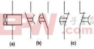
### Third, the Working Principle of Time Delay Relay – Graphic Symbol

### Fourth, the Working Principle of the Time Delay Relay – Power Failure Delay, Power On Delay, and Delay Intermediate
When the rated voltage is applied, the internal relay of the time delay relay and the two delay relays operate instantly. The power supply and timing circuit are de-energized, improving the relay's anti-interference performance. When the input voltage drops significantly or disappears, the momentary relay returns instantly, while the delay relays remain active. The contacts also return instantly, allowing the energy storage power supply to activate the timing loop. Crystal oscillation generates a clock pulse, which is divided into 10ms timing pulses. The counter counts these pulses, and when the count matches the set value, the drive relay returns, completing the function of delayed return after power failure.
#### 1. Power Off Delay
**(1) Introduction:**
The power-off delay relay is used in relay protection and automation for AC operations. It serves as a time component for delayed return after a sudden (DC) power cut.
**(2) Technical Requirements:**
- **Delay Range:** 0.02–5.00s (0.01s step), 0–999s (1s step).
- **Operating Voltage:** DC ≤ 70% of rated voltage; AC ≤ 80%.
- **Contact Capacity:** For DC, ≤250V, ≤1A, 5ms time constant; for AC, ≤250V, ≤5A, power factor 0.4±0.1.
- **Power Consumption:** ≤5W/7VA.
- **Insulation Performance:** 1kV/50Hz for 1 minute between open points, 1kV/50Hz for 2 minutes between different sets of contacts. Insulation resistance ≥100MΩ.
#### 2. Power On Delay
**(1) Introduction:**
The power-on delay relay is used in secondary circuits for relay protection and automatic control. It provides a delay function, with a range from 0.02–9.99s, 0.02–99.99s, and 0.02s–999h. It is a rail-type static relay with high precision and low power consumption.
**(2) Technical Requirements:**
- **Delay Accuracy:** Average error ≤0.1% + 3ms; consistency ≤3–10ms.
- **Working Voltage:** ≤70% of rated voltage.
- **Return Time:** ≤25ms for DC.
- **Return Voltage:** ≥10% of rated voltage.
- **Power Consumption:** ≤2.5W/4.5VA.
#### 3. Delay Intermediate Relay
**(1) Introduction:**
This relay is used in various protection and control systems as an auxiliary relay to increase contact number and capacity. It allows for adjustable power-on or power-off delay.
**(2) Technical Parameters:**
- **Environmental Conditions:** 20±2°C, 45–75% RH.
- **Usage Conditions:** -10°C to +50°C, ≤90% RH, ≤2,500m altitude.
- **Power Consumption:** ≤7VA at 380VAC, ≤4VA at 220VAC.
- **Contact Capacity:** DC 250V, 50W; AC 250V, 1200VA.
- **Insulation Resistance:** ≥10MΩ at 1000V.
- **Withstand Voltage:** 2000V between terminals, 1000V between contacts.
- **Electrical Life:** 10,000 cycles under rated load.
- **Mechanical Life:** 3 million cycles without load.
In summary, a **power-on delay** means the contact delays its action when the coil is energized and resets immediately when the power is off. A **power-off delay** means the contact acts immediately when the coil is energized and delays its return when the power is cut. A **delayed contact** refers to either a power-on or power-off delay.
Solar Carport System,Solar Carport Structural,Carport Solar Parking,Custom Car Parking Solar Carport Structural
Hebei Jinbiao Construction Materials Tech Corp., Ltd. , https://www.pvcarportsystem.com