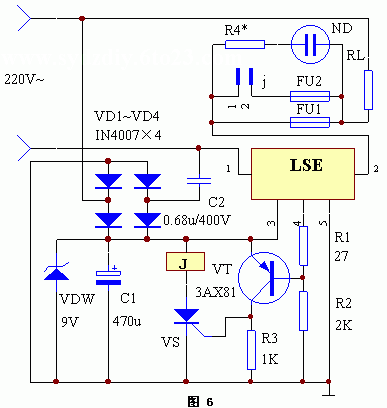
The circuit operation principle of the device is shown in the following figure. When the fuse FU1 is intact, the bubble ND is short-circuited and not lit, and the LSE pin 1 and pin 2 are connected. At this time, the LSE pin 4 outputs a high level, the triode VT is turned off, and the one-way thyristor VS has no trigger current does not work. Relay J has no current and does not pull in. Once FU1 is blown, the circuit of the 1st and 2nd legs corresponding to the LSE is disconnected, so the 4th pin of the LSE outputs a low level, the transistor VT is turned on, and the voltage generated on the resistor R3 drops to make the VS turn on and self-lock, relay J Excitation pull-in, the second fuse FU2 is turned on, and the load RL continues to work. If the second fuse FU2 is blown again, the bubble ND is lit at this time, indicating that there is a fault in the circuit, and the power should be applied after the repair, so as to avoid causing a larger fault.
This article refers to the address: http://

Wall Socket,USA Wall Socket,Internet Wall Socket
Normal Size PSU(S Series),Constant Voltage( SMV series) Co., Ltd. , http://www.chpower-supply.com