1. MOS Tube Working Principle – An Introduction to MOS Tube
The MOS tube, short for Metal-Oxide-Semiconductor Field-Effect Transistor, is a fundamental component in integrated circuits. It operates by controlling the flow of current through a channel using an electric field. The structure consists of a semiconductor layer, typically silicon, with a thin layer of silicon dioxide (an insulator) and a metal gate on top. This design allows the device to function as a voltage-controlled switch.
2. MOS Tube Working Principle – Structural Features of MOS Tube
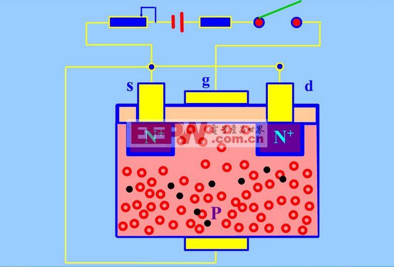
The internal structure of a MOS transistor is designed to allow unipolar conduction, meaning only one type of charge carrier (either electrons or holes) participates in the current flow. Unlike small power MOSFETs that are usually lateral devices, power MOSFETs often use a vertical structure, known as VMOSFET, which enhances their ability to handle high voltages and currents.
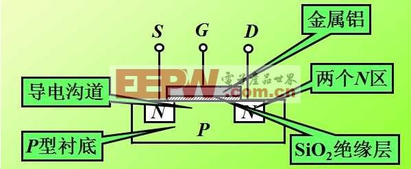
A key feature of the MOSFET is the presence of a silicon dioxide layer between the gate and the channel, resulting in a very high input resistance. When the gate-source voltage exceeds the threshold voltage, an n-type channel is formed, allowing current to flow between the source and drain. This makes the MOSFET ideal for switching applications due to its low power consumption and fast response time.
3. MOS Tube Working Principle – Characteristics of MOS Tube
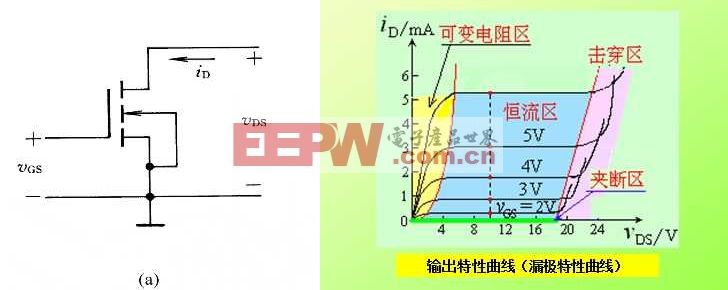
3.1 Input and Output Characteristics
In a common source configuration, the gate is isolated from the source by the oxide layer, so no gate current flows. The output characteristics show how the drain current changes with the drain-source voltage for different gate-source voltages.
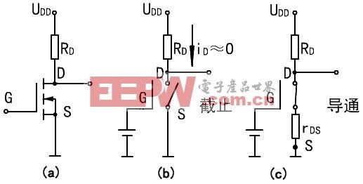
3.2 Conduction Characteristics
MOSFETs operate in either an on or off state when used as switches. For example, an NMOS transistor turns on when the gate-source voltage is above a certain threshold, making it suitable for low-side switching. On the other hand, PMOS transistors turn on when the gate-source voltage is below a certain value, making them ideal for high-side switching. However, due to higher on-resistance and cost, NMOS is more commonly used in high-end applications.
4. MOS Tube Working Principle
The working principle of an N-channel enhancement MOSFET involves controlling the amount of induced charge in the channel using the gate-source voltage. When the gate voltage is sufficient, it creates a conductive path between the source and drain, allowing current to flow. As the gate voltage increases, the channel becomes wider, increasing the drain current. This voltage-controlled behavior makes MOSFETs highly efficient for switching applications.
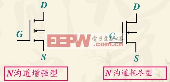
Classification of MOS Tubes
MOSFETs can be classified based on the type of channel (N-channel or P-channel) and the mode of operation (depletion or enhancement). N-channel depletion and enhancement types are widely used, as are P-channel variants. Each type has unique characteristics that make it suitable for different applications.

MOS Tube Application
MOSFETs are widely used in modern electronics due to their excellent switching performance. They are found in power supplies, motor drivers, and lighting control systems. Additionally, CMOS image sensors, which rely on MOS technology, have significantly improved camera image quality, making photography more accessible to everyone.
MOS Tube Working Principle – Reference Materials
1. MOS Tube Switching Loss – Flyback Analysis
Description: Understanding switching losses in MOSFETs using flyback analysis.
2. How MOSFET Works
Description: A detailed look at the structure and operation of power MOSFETs.
3. Difference Between MOS and Triode When Used as a Switch
Description: Comparing the performance of MOSFETs and triodes in switching applications.
Ring Common Mode Inductor,UU Common Mode Inductor,Vertical Plug-in Common Mode Inductor,Power Line Common Mode Choke
Xuzhou Jiuli Electronics Co., Ltd , https://www.xzjiulielectronic.com