Siemens TP series touchscreens run on the Windows CE operating system, featuring a 256-color display. These devices are known for their powerful functions, excellent visual performance, and high cost-effectiveness. They are compatible with most PLCs in the market, especially the Mitsubishi FX series, which is widely used in China. By leveraging the strengths of both systems, they complement each other well. However, in real-world applications, configuring alarm messages can be quite complex. This article provides a detailed guide on how to configure alarm messages using ProTool configuration software.
One of the key steps in displaying alarm messages is to drive the bits of the data pointer defined in the configuration software within the PLC program. When connecting Siemens TP series touchscreens with the FX series (excluding FX3U), there are two main scenarios for configuring alarm messages. Below, we'll walk through the design methods in detail.
2. Design Method
2.1 Short Alarm Message Configuration
(1) Communication Setup: Make sure to use the IF2 interface (RS-232 standard) and connect the FX series PLC with the SC-09 download cable. In the "Controller" settings under "Parameter Settings," set the interface to IF2, as shown in Figure 1.
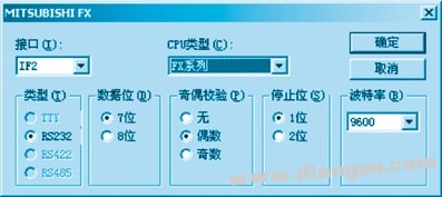
Figure 1: Communication Settings
(2) Add an "Alarm Message" to the area pointer. For example, you can use D32 to define 32 alarm messages. Since each D register has 16 bits, ProTool assumes that 32 × 16 = 512 alarm messages have been configured. In this case, only 32 are used. Refer to Figures 2 and 3 for details.
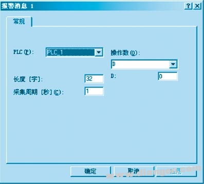
Figure 2: Area Pointer Settings

Figure 3: Alarm Message Configuration
(3) Enter the message content in the "Alarm Message" section, as shown in Figure 4.
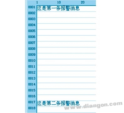
Figure 4: Writing Alarm Message Content
When filling out the alarm message content, if you want to simplify things, just fill in area pointers like D0.0, D1.0, D2.0, etc., as shown in the image below.

(4) PLC Program Design: When an alarm occurs, send the constant 1 to D0 to display the first alarm message. Send 1 to D1 to show the second alarm message. When the user confirms the alarm, remember to send 0 to D0, D1, etc.

Figure 5
This method allows you to display and clear alarm messages by driving the lowest bit of the specified D register.
2.2 Configuring Many Alarm Messages
If many alarm messages are needed, follow this section. The ProTool settings remain the same, but the way to drive D registers in the PLC differs. In the previous example, 16 bits of D were used as the area pointer, but only the lowest bit was utilized, leaving 15 bits unused. To make better use of these bits:
When sending a constant to D in the program, not only 1 should be sent, but each bit of the 16-bit D should have a chance to be set. For instance, in Figure 5, the area pointer covers bits 0–13 of D0. To display the second alarm message, set bit 1 of D0 to 1 and others to 0. For the third message, set bit 2 to 1, and so on.
According to binary rules, setting each bit of the data register sequentially to 1 corresponds to the following decimal values: 1 (bit 0), 2 (bit 1), 4 (bit 2), 8 (bit 3), etc. In the PLC program, when the number 1 is sent to D0, the first alarm is displayed. Sending 2 displays the second, 4 the third, and 8 the fourth.
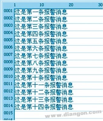
Figure 6: Multi-message Area Pointer Settings
Here, 14 alarm messages are configured. The corresponding PLC program (Figure 7) uses X0–X3 as trigger conditions and the ANS instruction to drive S900–S903. Each alarm message is displayed by sending 1, 2, 4, and 8 respectively.
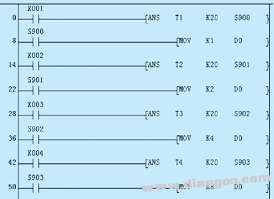
Figure 7: PLC Ladder Diagram
In the next part, the alarm is reset by turning on M1. Note that both ANR and transferring 0 to D0 must be done simultaneously.

Figure 8
If multiple D registers are used as area pointers for alarm messages, all D registers should be set to 0, as shown in the example below.

Figure 9
3. Conclusion
By following the above steps, the alarm message configuration has been successfully completed. This enables the full utilization of the TP series touchscreen's capabilities, allowing it to perform efficiently even when connected to non-Siemens PLCs. With proper setup, the system becomes more flexible and powerful, suitable for a wide range of industrial automation applications.
Tractor Autopilot Navigation,Gps Navigation System,Gps Autopilot,Unmanned Driving System
Xuzhou Jitian Intelligent Equipment Co. Ltd , https://www.jitianintelligent.com