All oscilloscopes generate vertical noise during both analog channel and digital conversion, which is unavoidable. Many users ignore this important parameter when purchasing an oscilloscope, and even oscilloscope vendors deliberately avoid this indicator, which is rarely clearly indicated in the data sheet. Here we will analyze the origin of vertical noise in detail and compare the noise floor characteristics of different models of oscilloscopes.
Where does the vertical noise come from?
The vertical noise of an oscilloscope comes mainly from two aspects:
1) Noise of the analog front-end circuit: including the noise of the attenuation circuit, the noise of the buffer circuit, the noise of the amplifier, and the noise of the power supply.
Because of the unboundedness and randomness of random noise, the higher the bandwidth, the wider the noise spectrum, and the greater the noise of the analog front-end circuit. The baseline noise floor of the oscilloscope is mainly determined by this part, which is also an important indicator to evaluate the design of the analog front end.
2) Noise generated by the analog signal digitization process: mainly the quantization noise of the ADC.
Regarding the quantization noise of ADC, Bell Labs' WR Bennett published a classic paper in 1948 with a well-known formula that can be characterized: 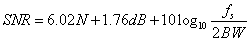
Take the ADC used in the ZDS2022 as an example. Its resolution is 8bit, the sampling rate is 1GSa/s, and the bandwidth is 200MHz. The signal-to-noise ratio of the ADC quantization process is 53.9dB. Therefore, the effective value of the quantization noise in the minimum vertical position of 2mV/div is 14uVrms, which is basically negligible. In this gear, the noise mainly comes from the analog front end. When measuring a square wave of 10mVpp, the waveform trace will become thicker, and the measurement error mainly comes from the noise floor of the analog front end.
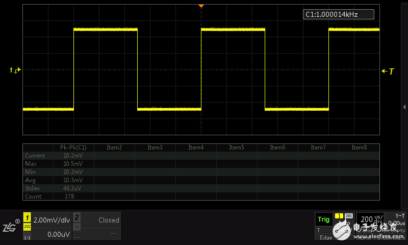
Figure 1 Square wave peak-to-peak error of 10mVpp tested in 2mV/div gear position
However, as the vertical gear is larger, the quantization noise gradually dominates, while the analog front-end noise will change slightly with the gain of the amplifier, but it is still below 2mV.
The oscilloscope usually prevents the ADC from exceeding the limit, leaving a margin of ±1 div. The actual vertical amplitude range is 10 div. Therefore, the 1LSB of the ADC is about 40 mV in the 1 V/div position. The ZDS2022 is calculated according to the maximum quantization error of ±0.5 LSB. The quantization noise under the gear is 40mVpp. A square wave signal with an amplitude of 5 Vpp is measured, and the measurement error mainly comes from quantization noise.
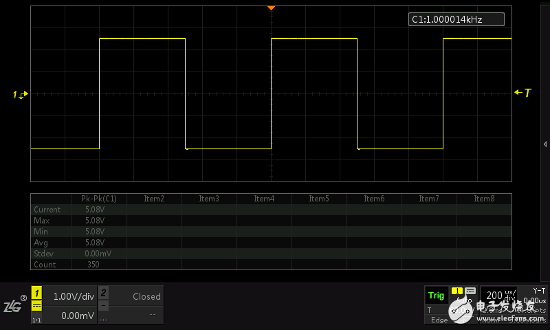
Figure 2 1V/div gear position test peak-to-peak error of 5Vpp square wave signal
What is the impact of vertical noise?
The vertical noise of the oscilloscope affects the accurate measurement of the signal in many ways. It will:
1) Introducing amplitude measurement error;
2) Introduce sin(x)/x waveform reconstruction uncertainty;
3) When performing small signal measurement, it will cause trigger jitter and cannot stabilize the waveform. In this case, trigger coupling must be set to high frequency suppression, and the trigger sensitivity should be appropriately increased.
4) Produce a "fat waveform" that is poorly displayed.
How to evaluate the noise floor of the oscilloscope?
Since the noise floor is so important, how do you evaluate the noise floor of an oscilloscope? The baseline noise floor of an oscilloscope is generally considered to be measured at the highest sensitivity of the oscilloscope's vertical position. However, many oscilloscopes on the market have the highest sensitivity, and the bandwidth is usually reduced because the amplifier gain is greater than 40dB. Therefore, to compare the noise floor of different oscilloscopes, the oscilloscopes with the same bandwidth characteristics should be put together to compare the baseline noise floor of the highest sensitivity gears under full bandwidth conditions.
Because the noise obeys the Gaussian distribution, there is randomness and unboundedness. The more data collected in the noise measurement, the higher the noise peak-to-peak offset. For this reason, random phenomena such as vertical noise and random jitter should use RMS ( Root mean square values ​​are used for definition and measurement.
In order to compare the baseline noise floor of each company's different models of oscilloscopes, you need to put their various settings as close as possible, the steps are as follows:
1) Open channel 1, set to DC coupling, set the input impedance to 1MΩ, turn off the bandwidth limit, and place it in the 2mV/div vertical position;
2) Disconnect the probe, ground the input port, and away from noise sources that may be coupled in;
3) Set the time base gear to 20ns/div, and choose the approximate value for the storage depth;
4) Set the trigger channel and trigger level correctly;
5) Turn off other channels (some models of oscilloscopes share the single-chip ADC and memory chip in multiple channels, which will reduce the sampling rate, memory depth and other parameters when multiple channels are turned on).
6) Turn on the oscilloscope's measurement function and select the voltage RMS (AC-AC) measurement;
7) For the sake of comparison, set the afterglow time to 10s.
The figure below shows the baseline noise floor results of the MDS3054 of the ZDS2022, T company (for the bandwidth consistency, the 250MHz bandwidth limit has been turned on) and the MSO-X 3012A test of the company A.
Figure 3 ZDS2022 noise floor test
Mono panel,High Quality Mono panel,Mono panel Details, Yangzhou Bright Solar Solutions Co., Ltd.
Yangzhou Bright Solar Solutions Co., Ltd. , https://www.solarlights.pl