MSP430G2553 system clock and oscillator
The clock system is supported by a basic clock module that supports a 32768Hz watch crystal oscillator, an internal ultra low power low frequency oscillator and an internal digitally controlled oscillator (DCO). The basic clock module is designed to meet both low system cost and low power requirements. The internal DCO provides a fast turn-on clock source and is stable in less than 1μs. The basic clock module provides the following clock signals:
• Auxiliary clock (ACLK), which is sourced by a 32768Hz watch crystal or an internal LF oscillator.
• Master clock (MCLK), the system clock used by the CPU.
• System Subclock (SMCLK), the subsystem clock used by the peripheral modules.
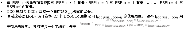
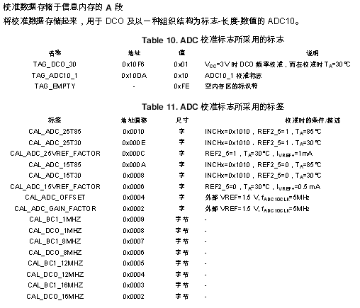
The DCO setpoint used to calibrate the DCO output frequency is stored in section A of the information memory.
Main DCO characteristics
MSP430G2553 clock
1, MSP430G2553 can achieve ultra-low power consumption, a reasonable clock module is indispensable. But the powerful clock module is also relatively complicated to set up.
2, MSP430G2553 clock source is:
(1), external low-frequency crystal oscillator LFXT1CLK: low-frequency mode connected to the watch crystal 32768Hz, high-frequency mode 450KHz ~ 8MHz;
(2), external high-speed crystal oscillator XT2CLK: 8MHz;
(3), internal digital control oscillator DCO: is a controllable RC oscillator, the frequency is 0~16MHz;
(4), ultra low power low frequency oscillator VLO: uncontrollable, 4~20KHz typical value is 12KHz;
3, clock module: 430 clock module has MCLK SMCLK ACLK:
(1) Main system clock MCLK: CPU clock supplied to the MSP430. Can be from LFXT1CLK XT2CLK DCO VLO is optional, the default is DCO.
(2) Subsystem clock SMCLK: Provided to high speed peripherals. Can be from LFXT1CLK XT2CLK DCO VLO is optional, the default is DCO.
(3), auxiliary system clock ACLK: is provided to low-speed peripherals. Available from the LFXT1CLK VLO.
4. The internal oscillator DCO and VLO provide a clock frequency that is not very accurate and varies greatly with the external environment.
7. After the system is powered on, the DCO clock is used by default. The default frequency of DCO is about 800KHz, but I use the oscilloscope to observe about 1.086MHz. When the DCO is set too high, the oscilloscope can see that the waveform is no longer square. Wave, but similar to a sine wave.
The DCO can be relatively precise with the macro definition provided by CCS, as follows:
DCOCTL = CALDCO_12MHZ; //DCO is set to 12MHz. This method sets the DCO frequency to be more accurate. The actual measured sine wave is about 12.08MHz.
BCSCTL1 = CALBC1_12MHZ;
In this way, you can set 1, 8, 12, 16MHz.
The macro is defined as follows:
#ifndef __DisableCalData
SFR_8BIT(CALDCO_16MHZ);
SFR_8BIT(CALBC1_16MHZ);
SFR_8BIT(CALDCO_12MHZ);
SFR_8BIT(CALBC1_12MHZ);
SFR_8BIT(CALDCO_8MHZ);
SFR_8BIT(CALBC1_8MHZ);
SFR_8BIT(CALDCO_1MHZ);
SFR_8BIT(CALBC1_1MHZ);
#endif
Our Terminal Blocks can be divided into these series(as follow),With the increasing degree of industrial automation and increasingly strict and precise industrial control requirements, the use of terminal blocks is gradually increasing:
PC-412 series Plug-in Terminal Blocks
PCT-412 series Mini Plug-in Terminal BlocksEU series Terminal Blocks
PL-102 series Plug-in Terminal Blocks
NRU series Terminal Connector Boxes
BH series Terminal Connector Boxes
H type Terminal Connectors
U(W) type Terminal Connectors
JXB/JB Terminal Block
EK Terminal Block
UK Terminal Block
TB series Terminal Connector
TC series Terminal Connector
Bus-Bar Terminals
10x1 PC Terminal Blocks
5x1 PC Terminal Blocks
LT Terminal Blocks
BHS07 Brass Bars
Terminal Blocks,Terminal Block Connector,Bus Bar Terminal,Electrical Terminal Block
Ningbo Bond Industrial Electric Co., Ltd. , https://www.bondelectro.com