In view of the above problems, this paper proposes a remote meter reading system structure based on Web and hardware reconfigurable technology. In terms of software, it uses an embedded Web server in the data concentrator to be responsible for data transmission tasks, and uses HTTP as the communication protocol. The client is a web browser that comes with the operating system, which can solve the compatibility problem caused by different communication protocols between various systems, and saves the software development cost of the meter reading client. On the hardware side, the data concentrator is implemented on a single FPGA chip using hardware reconfigurable technology and an IP core-based design method. Even if the system needs to be improved and upgraded in the future, it is only necessary to modify the configuration file of the FPGA chip without scrapping the entire hardware system, thereby protecting the existing hardware investment and reducing the maintenance cost of the system. In addition, the communication interface on the data concentrator can also be easily changed with the help of hardware reconfiguration technology, so it can adapt to various hardware environments.
Architecture of the remote meter reading system The architecture of the Web-based remote meter reading system is shown in Figure 1 (taking an electric meter as an example).
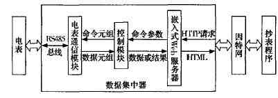
Figure 1 The architecture of the Web-based stopwatch system
It consists of three parts, namely the meter reading client program, the data concentrator and the electricity meters distributed in each household. The meter reading process is as follows: First, the meter reading staff uses the meter reading client program to send a meter reading request to the data concentrator in the form of HTTP protocol. After the request reaches the data concentrator through the Internet, it is first processed by an embedded Web server . The embedded Web server will return an HTML file to the client, asking the user to enter the command type (for example, whether to copy data or perform related control operations), the meter number, and additional data. After the user completes the form, the data will be sent to the embedded Web server in the data concentrator according to the HTTP POST protocol. Subsequently, the relevant commands and data parameters are extracted and sent to the control module of the data concentrator. The control module will make judgments and security checks on the command parameters, and then generate corresponding command tuples to control and read the data. The meter communication module completes the communication task with the meter, and is responsible for sending the command tuple to the meter and reading the execution result. When the meter reading operation is performed, the data will be returned to the control module in the form of data tuples by the meter communication module, and then assembled into a string according to a fixed format and handed over to the embedded Web server. The embedded Web server inserts these data into the pre-designed HTML file template, and then returns it to the client's meter reading program through the Internet.
The hardware design can be seen from Figure 1. The data concentrator is a key part of the system. On the one hand, it needs to collect data from the meter through the RS485 bus in accordance with "DL / T64521997: Multi-function Energy Meter Communication Protocol" and perform various Control tasks; on the other hand, it must be able to interpret the control commands sent in the form of HTTP and return the execution results to the meter reading client in the form of HTML files.
This article adopts the design method based on IP core when carrying on the hardware design, and realizes most functions of the data concentrator on a single FPGA chip. Before designing the circuit schematic diagram, an appropriate IP core must be selected according to the system requirements. The so-called IP core refers to those hardware circuits with specific functions that exist in the form of hardware (silicon layout) or software (RTL or gate-level models described in Verilog and VHDL). IP cores are usually divided into hard core, solid core and soft core. According to the hardware development environment and performance requirements of the system, this article selects a series of soft core products developed by Altera, which are hardware modules described in Verilog language, allowing users to configure various parameters according to their needs, such as data path bandwidth, Priority is given to speed optimization or resource optimization, so the application is very flexible. The soft IP core products used in the system are Nios CPU, ROM, RAM, timer, universal asynchronous transceiver UART, and Avalon bus module for external function expansion. The Nios CPU is configured in 32-bit word-length mode with 256 A general-purpose register, operating frequency 33MHz; UART is configured to a baud rate of 14400bPs, 8 data bits, 2 stop bits, no parity. After the IP core is determined and set accordingly, the circuit schematic of the system needs to be designed. Figure 2 shows the internal hardware structure of the data concentrator composed of various IP modules. The ROM is used to store user programs, and the RAM is used as a storage space when the program is running. UART is responsible for communication with the outside of the system. They will be connected to the Nios CPU via an internal bus, thus forming a complete embedded hardware system. The next step after designing the circuit diagram is to select a suitable implementation carrier. Design methods based on IP cores are usually implemented using FPGA chips or directly on silicon chips. This article uses Altera's APEX20KE series FPGA chip, which can provide about 8000 logic block resources and up to 400Kb of ROM and RAM storage space. Because the FPGA chip has the characteristics of being changed repeatedly, it helps to improve and continuously upgrade the hardware system. In addition, by reconstructing the communication interface, for example, changing the UART to a CAN bus controller, the system can be compatible with more hardware environments.
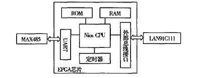
Figure 2 The hardware structure of the data concentrator Because it is difficult to construct a level conversion circuit, an Ethernet physical layer, and a MAC layer circuit on the FPGA chip, this article puts these functions outside the FPGA chip and uses MAX485 and LAN91C111 chips to implement Level conversion and Ethernet hardware interface functions. The UART module in the FPGA chip and the MAX485 chip work together to complete the data communication task with the ammeter. The former is responsible for receiving and sending data, and the latter is responsible for the signal level conversion. SMSC's LAN91C111 is specially designed to facilitate the connection of embedded application systems to Fast Ethernet. It implements the physical layer and media access control layer (MAC) of the CSMA / CD protocol, and can be easily connected with many The embedded processor exchanges data.
The software design data communication protocol meter reading system has two problems with the communication protocol, one of which is between the data concentrator and each electric meter. At present, most of the electricity meters produced by domestic manufacturers have the meter reading protocol specified by the "Multi-function Energy Meter Communication Protocol" promulgated by the country. Therefore, as long as the electricity meter communication mode in the data concentrator, another place where the communication protocol must be considered is data Between the concentrator and the power meter reading center. At present, the country has not formulated formal standards, and the protocols adopted by various manufacturers are also different. This has caused basically no interoperability and interconnectivity between systems, thus hindering the further development of the industry.
This article proposes to use the standard open HTTP protocol as the basis for application layer communication, which not only solves the compatibility problem between systems, but also introduces the widely used Web technology on the Internet to the remote meter reading system, bringing it to Many conveniences. For example, as long as you can connect to the Internet, you can complete the meter reading work, and get rid of the constraints of time and place. In addition, the terminal program used by users for meter reading is a Web browser on all computer platforms, which means that users do not need to spend a penny for additional investment to get a graphical user interface. The bottom layer of HTTP uses TCP / IP protocol to ensure the reliable transmission of data on the Internet. The user's operation commands and related parameters of the meter will be transmitted as HTML form data to the embedded Web server on the data concentrator by HTTP POST method, and the operation results and data will be returned in the form of HTML table.
Data concentrator software design The data concentrator plays a key role in the meter reading system. On the one hand, it must communicate with the meter reading center through the Internet, and on the other hand, it must collect electricity data from various meters. In order to reduce development difficulty and improve maintainability, the system uses C language as the development language, and uses GNU development tools, including gcc, gdb, etc. In addition, the system functions are decomposed into five mutually coordinated tasks, and uc / os-II is used as a real-time operating system to implement task scheduling and inter-task communication. The five tasks are:
(1) Network communication interface: responsible for sending and receiving data on the Internet. This article uses the simplified TCP / IP protocol stack provided by Altera for embedded system applications as the underlying communication protocol. The data sending function is implemented by calling the TCP / IP transport layer service function nr_ pLugs_send (), while the data receiving function is implemented by a callback function that is registered when the communication socket is created. When the transport layer receives a valid application layer data, the function is called, the application layer data pointer is passed as an actual parameter, and then the callback function sends the data pointer to the HTTP engine in the form of a message.
(2) HTTP engine: responsible for receiving and sending data in HTTPPOST protocol, and handing out the meter reading commands and data parameters extracted to the control module; according to the data returned by the control module and the HTML file template read from the virtual file system , Dynamically construct a complete HTML file and send it to the requester.
(3) Virtual file system: responsible for implementing a small read-only file system on ROM or external Flash memory to store various static Web pages and page templates needed for dynamically constructing Web pages. It relies on maintaining a file index table to achieve file reading, and its structure is shown in Figure 3.

Figure 3 Virtual file system index table (4) Control module: responsible for security check, command and data parameter format conversion. Since the Internet is a public network, the control commands and data transmitted on it may be intercepted, tampered, and retransmitted, so a security check is required. Mainly adopt two methods of data encryption and random number verification.
(5) Electric meter communication: It is responsible for communicating with the designated electric meter to read power consumption data and complete various control operations. Its function is equivalent to the data link layer in the layered network model. The receiving and sending of data is realized through two functions of nr_uart_rxchar () and nr_uart_Txchar ().
The client application design of the meter reading center has two different ways to complete the meter reading task: interactive and batch processing. In the interactive process, it is required to manually enter the information such as the meter number and the operation to be performed. After the query is completed, the data is manually transcribed into the database. For this method, the Web browser that comes with the operating system is a meter reading terminal program. However, the efficiency of interactive meter reading is low, and it is only suitable for occasions such as copying the power information of a specified user, performing control tasks on a user's electricity meter, or self-checking by the user. When a large amount of power data needs to be copied and received, a batch processing method is used. Figure 4 shows the program flow chart in batch mode. In the batch meter reading program, there are two key technical issues: one is to transmit the meter reading command to the embedded Web server on the data concentrator via HTTPPOST, and the other is to extract the electricity data from the received HTML file . For the first question, we first analyze the HTTP data packets captured by the network packet capture program (Sniffer program) to grasp the data format and the data format used by the browser and the Web server to transmit information between the browser and the PC server environment. Timing relationship, and then write a program in the VB environment to simulate the behavior of the browser in this process. For the second problem, the solution is to stipulate that the data is returned in the form of a table, and ensure that the format is fixed. Therefore, by searching HTML tags such as HTML files, the power data can be extracted.
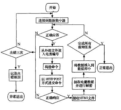
Figure 4 Batch meter reading process Other functions of the meter reading center, such as electricity bill calculation, data query and statistics, and system maintenance, are all common database applications. Due to space limitations, I will not introduce them one by one.
Conclusion Based on the analysis of the structure of the existing remote meter reading system, this paper proposes a new remote meter reading system structure based on Web and hardware reconfigurable technology, and uses the design method based on IP core for hardware design to make It has the characteristics of strong compatibility, small size, low power consumption, easy upgrade and maintenance. At present, the key part of the meter reading system, the data concentrator, has been successfully implemented on a single FPGA chip and completed the communication test between it and the meter reading terminal program. We are now building a complete prototype system for further testing and improvement.
Qunsuo are dedicated in Industrial PDA, our PDAs are durable and long time standby. We can provide handheld Barcode Scanner Pda, PDA with built in printer and so on. All of our PDA provide with demo app and free SDK, supporting our customers for use easily. We can provide our customers prompt after-sales service about any technical supports. Our PDA support many functions, including RFID reader, NFC reader, Barcode Scanner, UHF reader, fingerprint scanner, IC card reader, PSAM and etc. And also if you have any PDA OEM/ODM requirements, we can also help you to make prototype into physical.

Industrial PDA
Barcode Scanner Pda,Pda Scanner Android,Pda Printer Scanner,Pda Android 2D Barcode Scanner
Shenzhen Qunsuo Technology Co., Ltd , https://www.qsprinter.com