The overall market trend for industrial motor drives is the ever-increasing demands for greater efficiency, reliability and stability. Some trade-offs to increase the conduction loss of insulated gate bipolar transistors (IGBTs) are: higher short-circuit current levels, smaller chip sizes, and lower thermal capacity and short-circuit withstand times. This highlights the importance of gate driver circuits and overcurrent detection and protection. The following discusses the successful and reliable implementation of short-circuit protection in modern industrial motor drives, while providing an experimental example of an isolated gate driver for three-phase motor control applications.
What are the short circuits in the industrial environment?
Industrial motor drives have a relatively harsh operating environment and can experience high temperatures, AC line transients, mechanical overloads, wiring errors, and other unexpected conditions. Some of these events may cause large overcurrents to flow into the power circuit of the motor drive. Figure 1 shows three typical short circuit events.
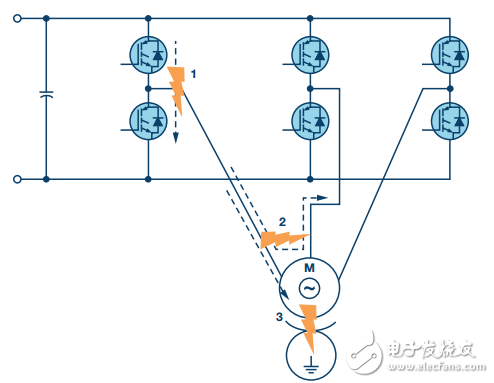
Figure 1. Typical short circuit event in an industrial motor drive
They are:
The inverter is straight through. This may be caused by incorrectly turning on two IGBTs of one of the inverter arms, which may be due to electromagnetic interference or controller failure. It may also be caused by one of the IGBT wear/faults on the arm, while the normal IGBT remains switched.
Short circuit to phase. This may be caused by a performance breakdown, excessive temperature or an overvoltage event that causes an insulation breakdown between the motor windings.
The phase line is shorted to ground. This may also be caused by a performance breakdown, excessive temperature or an overvoltage event that causes an insulation breakdown between the motor windings and the motor casing.
In general, the motor can absorb very high currents for a relatively long period of time (milliseconds to second, depending on the size and type of the motor); however, the IGBT, the main part of the industrial motor-driven inverter stage, is short-circuited. The withstand time is in the order of microseconds.
IGBT short circuit withstand capability
The IGBT short-circuit withstand time is related to its transconductance or gain and the thermal capacity of the IGBT chip. Higher gains result in higher short-circuit currents within the IGBT, so it is clear that lower gain IGBTs have lower short-circuit levels. However, higher gains also result in lower on-state conduction losses, and trade-offs must be made. 1 The development of IGBT technology is contributing to the increase in short-circuit current levels, but the tendency to reduce short-circuit withstand time. In addition, advances in technology have led to smaller chip sizes, 2 reduced module size, but reduced thermal capacity, and further reduced tolerance time. In addition, it has a large relationship with the IGBT collector-emitter voltage, so the parallel trend of industrial drive tends to higher DC bus voltage levels further reduces the short circuit withstand time. In the past, this time range was 10 μs, but in recent years the trend has been in the direction of 5 μs3 and under certain conditions down to 1 μs. 4 In addition, the short-circuit withstand time of different devices is also quite different, so for IGBT protection circuits, it is generally recommended to build more margin than the rated short-circuit withstand time.
IGBT overcurrent protection
Regardless of property damage or safety considerations, IGBT protection for overcurrent conditions is the key to system reliability. IGBTs are not a fail-safe component. If they fail, they can cause the DC bus capacitor to explode and cause the entire driver to malfunction. 5 Overcurrent protection is typically achieved by current measurement or desaturation detection. Figure 2 shows these tips. For current measurement, both the inverter arm and the phase output require measurement devices such as shunt resistors to handle shoot-through faults and motor winding faults. The fast execution of the trip circuit in the controller and / or gate driver must turn off the IGBT in time to prevent the short circuit withstand time. The biggest benefit of this method is that it requires two measuring devices on each inverter arm and is equipped with all relevant signal conditioning and isolation circuits. This can be alleviated by simply adding a shunt resistor to the positive DC bus line and the negative DC bus line. However, in many cases, there are either arm shunt resistors in the driver architecture or phase shunt resistors to serve the current control loop and provide motor overcurrent protection; they are also possible for IGBT overcurrent protection – provided that The signal conditioning response time is fast enough to protect the IGBT during the required short-circuit withstand time.
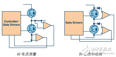
Figure 2. Example of IGBT overcurrent protection technology
The desaturation detection uses the IGBT itself as a current measuring element. The diodes in the schematic ensure that the IGBT collector-emitter voltage is only monitored by the sense circuit during turn-on; during normal operation, the collector-emitter voltage is very low (typically 1 V to 4 V). However, if a short circuit event occurs, the IGBT collector current rises to a level that drives the IGBT out of the saturation region and into the linear operating region. This causes the collector-emitter voltage to rise rapidly. The above normal voltage levels can be used to indicate the presence of a short circuit, while the desaturation trip threshold level is typically in the 7 V to 9 V region. Importantly, desaturation can also mean that the gate-emitter voltage is too low and the IGBT is not fully driven to the saturation region. Care should be taken when performing desaturation detection deployment to prevent false triggering. This may especially occur during the transition from the IGBT off state to the IGBT on state when the IGBT has not fully entered saturation. The blanking time is usually between the turn-on signal and the desaturation detection activation time to avoid false detection. A current source charging capacitor or RC filter is also typically added to create a short time constant in the detection mechanism to filter the filter spurs caused by noise pickup. When selecting these filter components, a trade-off is required between the noise immunity and the IGBT short-circuit withstand time.
After detecting an IGBT overcurrent, a further challenge is to turn off the IGBT at an abnormally high current level. Under normal operating conditions, the gate driver is designed to turn off the IGBT as quickly as possible to minimize switching losses. This is achieved by a lower driver impedance and gate drive resistance. If the same gate turn-off rate is applied for overcurrent conditions, the collector/emitter di/dt will be much larger because the current will vary greatly in a shorter period of time. The parasitic inductance of the collector-emitter circuit due to stray inductance of the wire bonding and PCB traces may cause a large overvoltage level to instantaneously reach the IGBT (because VLSTRAY = LSTRAY & TImes; di/dt). Therefore, it is important to provide a high impedance turn-off path when turning off the IGBT during a desaturation event, which can reduce di/dt and all potentially damaging overvoltage levels.
In addition to short circuits caused by system faults, instantaneous inverter pass-through will also occur under normal operating conditions. At this time, the IGBT conduction requires the IGBT to be driven to the saturation region where the conduction loss is the lowest. This usually means that the gate-emitter voltage in the on state is greater than 12 V. The IGBT turn-off requires the IGBT to be driven to the active cut-off region to successfully block the reverse high voltage across the high-side IGBT when it is turned on. In principle, this can be achieved by reducing the IGBT gate-emitter voltage to 0 V. However, the side effects of the low-end transistor on the inverter arm when it is turned on must be considered. The rapid change of the switching node voltage during turn-on causes the capacitive induced current to flow through the low-end IGBT parasitic Miller gate-collector capacitance (CGC in Figure 3). This current flows through the low-side gate driver (ZDRIVER in Figure 3) to turn off the impedance, creating a transient voltage increase at the low-side IGBT gate emitter, as shown. If the voltage rises above the IGBT threshold voltage VTH, it will cause a brief turn-on of the low-side IGBT, resulting in a transient inverter arm pass-through - because both IGBTs are briefly turned on. This generally does not destroy the IGBT, but it can increase power consumption and affect reliability.
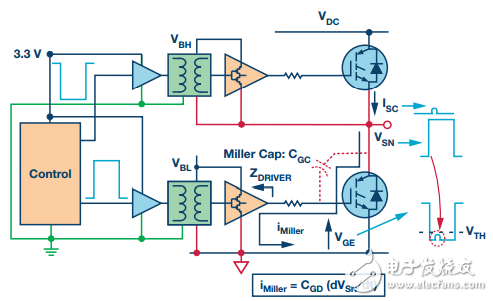
Figure 3. Miller Inductive Inverter Direct
In general, there are two ways to solve the inductive conduction problem of the inverter IGBT - using a bipolar power supply and / or an additional Miller clamp. The ability to accept a bipolar supply at the isolated side of the gate driver provides additional margin for induced voltage transients. For example, a –7.5 V negative rail indicates that an induced voltage transient greater than 8.5 V is required to sense stray conduction. This is enough to prevent stray conduction. Another method is to reduce the turn-off impedance of the gate driver circuit for a period of time after the turn-off transition is completed. This is called the Miller clamp circuit. The capacitive current now flows through the lower impedance circuit, which in turn reduces the magnitude of the voltage transient. The use of asymmetric gate resistors for turn-on and turn-off provides additional flexibility for switching rate control. All of these gate driver functions have a positive impact on the reliability and efficiency of the overall system.
Anti-reflection coating, also known as anti-reflection coating, its main function is to reduce or eliminate the reflected light of optical surfaces such as lenses, prisms, and plane mirrors, thereby increasing the amount of light transmitted by these components, reducing or eliminating stray light in the system, and anti-reflection coating It is an optical coating with a wide range of applications, widely used in daily life, industry, astronomy, military science, electronics and other fields.
Reflective film generally reads metal and medium, and both have a large extinction coefficient. When the light beam enters the metal surface from the air, the amplitude of the light entering the metal is rapidly attenuated, so that the light energy entering the metal is correspondingly reduced, and the reflection Light energy increases. The greater the extinction coefficient, the faster the light amplitude decays, the less light energy enters the metal, and the higher the reflectivity.
The function of the spectroscopic film is to generate multiple paths of light as several directional collimators to calibrate the optical path and improve the measurement accuracy. Considering the different spectral response curves of the light source and the receiving device diode array, the incident light in the optical path needs to pass through multiple spectroscopic film surfaces.
Filter film refers to a film layer that attenuates light intensity or changes the spectral composition. The main purpose is to reduce or increase the color temperature, change the wavelength, block unwanted light, change the color, etc.
Anti-Reflection Coating,Product Reflective Coating,Product Beam Splitter Coating,Product Filter Coatign Products
Bohr Optics Co.,Ltd , https://www.bohr-optics.com