Many microcontrollers now integrate A / D chips, but often fail to meet the requirements of the application, so they have to waste internal A / D resources and spend money to expand an A / D chip with higher accuracy. This design implements a method to improve the resolution of the existing ADC, and is suitable for the case where the resolution of the existing ADC does not meet the requirements and the accuracy requirements are not particularly strict.
1 Gradient mean A / D scheme
Definition 1 Let x be a real number, [x] represents the largest integer not greater than x, then call f (x) = [x] the rounding function of x.
Definition 2 Let x be a real number,
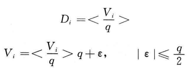
Obviously, letting V pass through the A / D system whose quantization unit is q is exactly equivalent to the quantization operation of x = V / q (denoted as D =

Let's call the A / D conversion part of it a basic quantization system, the stepped input signal is Vis, and its amplitude value

With equal gradients, the total amplitude is 1 quantization unit q, where m is a positive integer. The input signal V and the step wave signal Vis of the system are sequentially superimposed and sent to the basic quantization system, and the quantized output signal Di is output to the data processing unit for storage and processing. Taking the average value of the stable quantization output of 2m times Di of the basic quantization system as the system output, then there is the basic theorem of the gradient mean A / D scheme: let the quantization unit of the basic quantization system be q and the transfer function
Then the equivalent quantization unit of the A / D system shown in Figure 1 is q / 2m, and the transfer function is
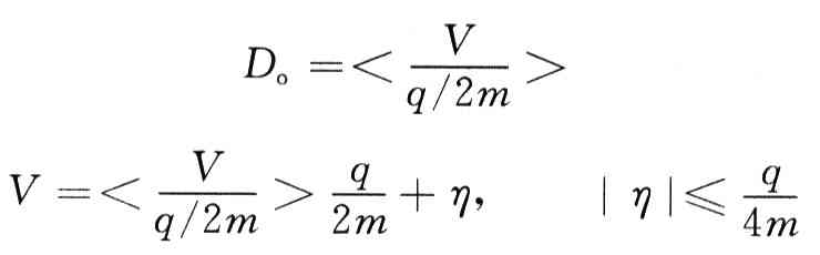
That is, the system capacity is expanded to 2m times the basic quantified system capacity.
Performance comparison of gradient mean method and statistical mean method:
â‘ The statistical mean method must read out the noise disturbed every time sampling. 1LSB bit, but it is unstable; while the gradient mean method only needs to read 1LSB bit per sample, which is stable. Therefore, the time taken for a single sampling is shorter than the former.
â‘¡Using the statistical mean method, if you want to get a stable 0.1LSB bit output, the noise level should be reduced to 1 / lO (according to σ (.x) âˆ1 / n), and you need to sample 100 times; while the gradient mean method only needs to sample 10 times, you can achieve the same effect.
â‘¢Adopt statistical mean method, with long response and low efficiency. For occasions with high real-time requirements and quick response, the gradient mean method is better.
2 System design
Use Zhou Ligong's EasyARM2131 development board, and design a simple peripheral circuit. The EasyARM2131 development board uses NXP's LPC2138 chip based on ARM7TDM1-S core, single power supply, LQFP64 package, with JTAG simulation debugging, ISP programming and other functions, providing RS232 interface circuit, I2C memory circuit, keyboard, LED, buzzer and other commonly used The functional components greatly facilitate the user's development experiment of 32-bit ARM embedded system. The resolution of A / D in LPC2138 is 10 bits, which can be expanded to 12 bits or even higher.
The principle diagram of the system is shown in Figure 2. The core of the peripheral circuit is the ladder wave generator and the in-phase adder.

2.1 Ladder wave generator
The D / A converter inside the LPC2138 is unipolar and can only generate unipolar stepped waves, while the gradient mean method requires the use of bipolar stepped waves. To this end, a differential op amp circuit is used, which not only converts the unipolar ladder wave to bipolar, but also steps down the voltage so that the total voltage amplitude of the ladder wave is a quantization unit of the A / D converter. The specific circuit is shown in the right half of Figure 3.

According to the principle of "virtual short", "virtual break" and superposition of operational amplifier
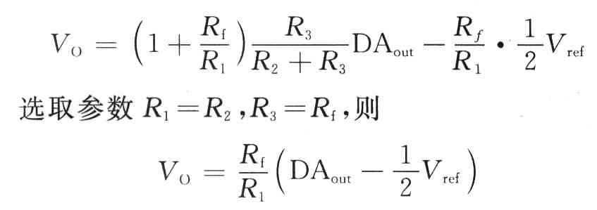
Among them, RF is a potentiometer, which can adjust the resistance and change the software settings to improve the accuracy of the A / D system. According to the design requirements, the resistance values ​​are R1 = R2 = 10 kΩ, R3 = Rf = 2.5 kΩ, and Rf / R1 = 1/4.
The amplitude and polarity conversion circuit needs to use (1/2) Vref, so it should be divided by the reference voltage source. In order to prevent the voltage from being pulled down, a voltage follower circuit is added, as shown in the left half of Figure 3. Among them, the parameter selection R8 = R9 = 10 kΩ, OP07 is used for the op amp.
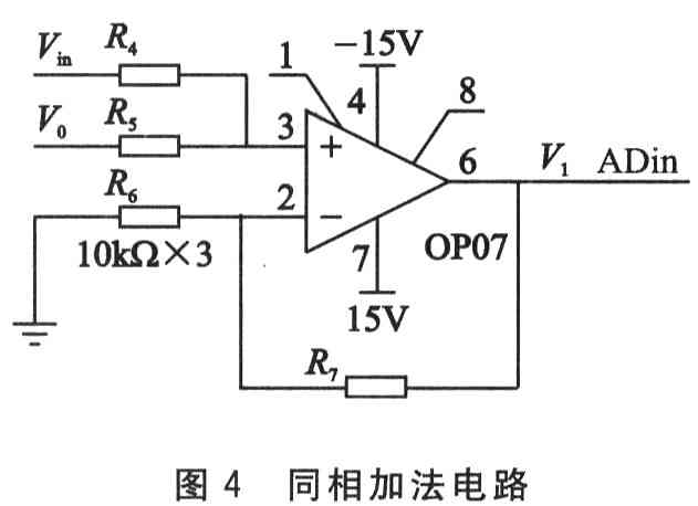
2.2 In-phase addition circuit
The in-phase addition circuit is shown in Figure 4. Parameter selection R4 = R5 = 1ckΩ, R6 = R7 = 10 kΩ, so V1 = Vin + V0, where Vin is the input voltage, V0 is the ladder wave voltage, and V1 is input to ARM internal processing.
The general diagram of the peripheral circuit is shown in Figure 5.

3 System software design
The software part is written in C language and uses ADSl. 2 Development environment, and transplanted μC / OS-II operating system. See references for details.
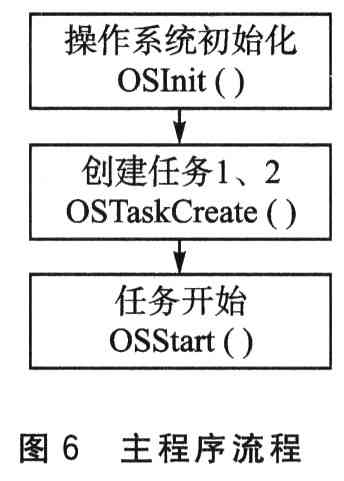
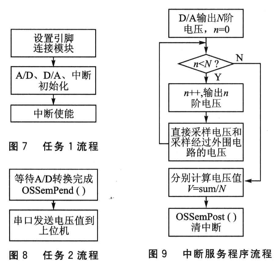
The program is mainly composed of the following parts: the main program, responsible for initializing the operating system and creating tasks; task 1, responsible for initializing the target board; task 2, responsible for the serial communication between the target board and the host computer; interrupt service program, responsible for sampling and calculating voltage. The flow of each part is shown in Figure 6 to Figure 9.
After testing, the voltage measured by the A / D system is more accurate than the directly measured voltage; the higher the resolution of the A / D system, the more accurate the measured voltage. Due to devices and processes, the system has certain errors, but basically meets the design requirements, proving that the A / D system using the gradient mean method is completely achievable. And if better technology and precise components are used, the accuracy of this A / D system can also be improved.
Micro motors Based on Dc Motor, Micro Motor belongs to the small size of dc motor,micro motor rotor, back cover, chassis, rotor winding is mainly copper, back cover most of the use of plastic material, motor shell use galvanized steel plate, the micro motor can be ROHS test.
A micro motor is any of a class of rotary electrical machines that converts direct current electrical energy into mechanical energy. The most common types rely on the forces produced by magnetic fields. Nearly all types of micro motors have some internal mechanism, either electromechanical or electronic, to periodically change the direction of current flow in part of the motor.


Micro motor is mainly used in: outdoor lamps, electronic toys, model aircraft, intelligent bin, breeze machine, etc


Method of use: the best stable in horizontal plane, installed on the Micro motor output shaft parts, cannot use a hammer to knock, knock prone to press into the micro motor drive, may cause damage to internal components, and cannot be used in the case of blocked.

Operating temperature range:
Micro motor should be used at a temperature of -10~60℃.
The figures stated in the catalog specifications are based on use at ordinary room temperature catalog specifications re based on use at ordinary room temperature (approximately20~25℃.


If a micro motor is used outside the prescribed temperature range,the grease on the gearhead area will become unable to function normally and the motor will become unable to start.Depending on the temperature conditions ,it may be possible to deal with them by changing the grease of the motor's parts.Please feel free to consult with us about this.
Storage temperature range:
Micro motor should be stored ta a temperature of -15~65℃.
In case of storage outside this range,the grease on the gearhead area will become unable to function normally and the motor will become unable to start.
Service life:
The longevity of micro motor is greatly affected by the load conditions , the mode of operation,the environment of use ,etc.Therefore,it is necessary to check the conditions under which the product will actually be used .The following conditions will have a negative effect on longevity.Please consult with us should any of them apply.
â—Use with a load that exceeds the rated torque
â—Frequent starting
â—Momentary reversals of turning direction
â—Impact loads
â—Long-term continuous operation
â—Forced turning using the output shaft
â—Use in which the permitted overhang load or the permitted thrust load is exceeded
â—A pulse drive ,e.g.,a short break,counter electromotive force,PWM control
â—Use of a voltage that is nonstandard as regards the rated voltage
â—Use outside the prescribed temperature or relative-humidity range,or in a special environment.
â—Please consult with us about these or any other conditions of use that may apply,so that we can be sure that you select the most appropriate model.
when it come to volume production,we're a major player as well .each month,we rurn out 600000 units,all of which are compliant with the rohs directive.Have any questions or special needed, please contact us, we have the engineer group and best sales department to service to you Looking forward to your inquiry. Welcome to our factory.

Micro Motor
Micro Motor,Micro Dc Motor,Micro Vibration Motor,Micro Electrical Motor
Shenzhen Shunchang Motor Co., LTD. , https://www.scgearmotor.com