introduction
Displaying an increasingly important feature in today's camera phones on a TV screen, because it allows you to watch your photos with friends and family more satisfactorily than ever before, and the TV output function can be relatively more Less cost is added to camera phones and provides important revenue opportunities for handset manufacturers.
The technical requirements of camera phones are far more challenging than typical video application technologies and require a trade-off between performance, power consumption, printed circuit board space and cost. The technical requirements in camera phones and TV set-top boxes stand in stark contrast. First, the set-top box is connected to the AC power supply, so the power consumption is not a big problem. Secondly, the video signal board is installed in a relatively large space, so the package size and the number of external components required are usually not so important. The set-top box power supply voltage is generally 5V (or higher) single power supply, so there is a large room for the video signal. However, in each of the above aspects of the camera phone, there are specific design constraints. In order to successfully design the TV output function into the camera phone, these design constraints and other technical and commercial requirements must be carefully considered.
The challenge of camera phone design
Video signal selection
Composite video (CVBS) output is the most commonly used signal in portable applications, and almost all new TV sets have composite video input jacks. Despite a slight performance advantage, there are fewer TVs with S or component video input. In addition, the slight improvement in image quality brought by S-Video is not enough to offset the power consumption in camera phone applications. Space and cost increase.
Frequency Response Although the NTSC/PAL system has a frequency range of only 5 MHz, a wideband amplifier is required to achieve a flat frequency response over this frequency range. Low pass or multipole filters are often required to reduce the "sampled product" of the video encoder. For example, digital-to-analog converters embedded in Texas Instruments' digital multimedia processors have been speeded up to 27MHz, so the "mirror frequency" produced by the 27MHz sampling frequency can be seen in the video signal spectrum. If no filtering is done, these sampled products will be folded into the video signal by video processing in the connected video device (e.g., a television) and produce undesirable image distortion on the television screen. Video amplifiers such as the OPA360, with an internal low-pass or multi-pole amplifier, can effectively attenuate the sampled product by passing the signal through without any image distortion.
Like the two-pole filter in the integrated OPA360 amplifier, it represents a good balance between the best possible attenuation of the sampled product and the reduction in chip size and solution cost. This solution typically provides 21dB at 27MHz. Attenuation while effectively reducing the sampled product.
Power consumption in critical mode
When a camera phone is operating in TV out mode, a typical video amplifier will consume 5-9 mA of supply current plus current for video line drive. Therefore, when selecting a video amplifier for a portable video device, the operating mode power consumption is an important factor that must be considered, but more importantly, the power consumption when the video function is not enabled, when it is desired to compare on a TV screen. When viewing photos satisfactorily, camera phones are typically only connected to a television or projector.
Therefore, video amplifiers suitable for camera phone applications must have a shutdown (or sleep) mode. To extend battery life and charge interval, the source current in shutdown mode varies widely throughout the industry and must be carefully selected during the product selection phase to ensure very low quiescent current in shutdown mode. For example, the OPA 360 has a static (or shutdown mode) current of less than 5A. Many other video amplifiers have a quiescent current of 50A or more.
Integrated Video Amplifier Solution
Since the printed circuit board (PCB) space in a camera phone is extremely limited, any video function block must be as small as possible. A solution with a video amplifier and the necessary discrete components may work, but in a camera phone. It doesn't work, so it's best to use a more integrated solution.
Modern integrated solutions save board space and reduce device count. Figure 1 is a schematic diagram of a conventional TV output function using a standard video op amp and necessary discrete components, including a large, high 220μF coupling capacitor. The capacitance in the circuit is very large and cannot meet the size and cost requirements of most camera phone designs. Although it is not a problem in applications where the board space such as the set-top box is large enough, in the camera phone, the "space" is extremely Tight, so you must consider ways to reduce the overall solution size. 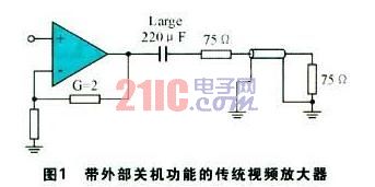
This article refers to the address: http:// |
|---|
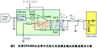
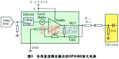
The OPA360 is a fully integrated video amplifier solution with a gain of 2 and an integrated two-pole filter and input level shifting circuit. It does not require any output capacitors to support DC-coupled outputs, further enabling the solution. The size is reduced to 5.5mm2. The only external component required is a very small 100nF power supply decoupling capacitor. Figure 2 shows the OPA360 and an AC-coupled output solution with a sink correction. In fact, if the in-line coupled output is used, two of the AC-coupling capacitors can be eliminated. Figure 3 shows the OPA360 amplifier circuit with DC-coupled output.
| ||
|---|---|---|
In the current mobile phone design, 5V single power supply is generally not used. The maximum power supply voltage is usually 3.3V, and sometimes lower. This low power supply voltage puts special requirements on the amplifier and its ability to output high quality video signals, and video. A 2Vp-p signal swing on the amplifier output also requires a lower supply voltage. The forward saturation limit must be increased to accommodate the field tilt in the output, so the minimum actual source voltage design limit in the sink-corrected AC-coupled solution is approximately 3.3V, since the DC-coupled output has no field tilt. Therefore, it can safely operate on a 2.8-3.0 source voltage.
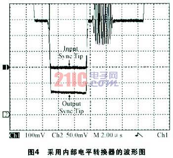
Many popular video DACs embedded in digital media processors (such as TI's digital media processors and new OMAP processors) can operate at low, single supply voltages. In general, video DACs have the lowest sync pulse output. Corresponds to 0V. Unfortunately, the output of a typical single-supply, high-speed op amp cannot swing down to 0V, so if driven with a 0V input, the amplifier's output stage will saturate and limit the bottom of the sync pulse, reducing the integrity of the video signal. And the IT company's OPA360 has a 60mV level shifter in the input stage and a 25mV ground-to-ground swing on the output with 150 video loads. This combination allows the amplifier to be continuously in the linear region. Work and provide complete video signals. The level shifter makes the OPA360 easy to DC-couple to the output without degrading video performance. Figure 4 shows the waveform after internal level shifting.
Output coupling selection
AC-coupled output with sink correction
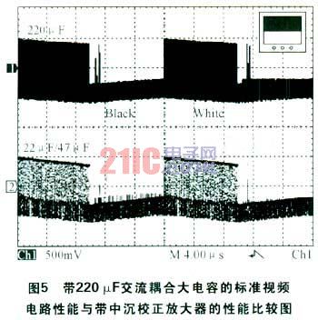
Since the beginning of television, AC coupling is a classic method for connecting video signals. If a design engineer chooses to use a conventional video amplifier for AC-coupled output, a large capacitor of 220μF or 470μF is needed. These capacitors are not only bulky but also bulky. Expensive, generally only used in devices with large space such as set-top boxes (for example), but in modern portable video applications, a technique called "sink correction" is usually used, and through two small output coupling capacitors. Instead of traditional large output capacitors to reduce the size of the entire solution, the traditional 220μF circuit produces a low frequency pole (3dB frequency) at 5Hz. If this capacitance is made small, the transition phase shift in the critical 50-100 Hz range will produce a field tilt, which in turn will interfere with the normal recovery of the sync signal in the television receiver, as low as a camera phone. Transition field tilt in single-supply voltage applications can cause output clipping and severely degrade video performance, such as the sink circuit used in the OPA360, which produces amplitude response peaks in the 20Hz region. This small amplitude peak, usually only a few tenths of a dB, compensates for the phase response in the critical 50-100 Hz range, greatly reducing field tilt. It should be noted that only two volumes and costs are required at this time. The much smaller capacitance makes it easy to install in a camera phone. For good video performance, a 22μF sink capacitor and a 47μF coupling capacitor can be used. Figure 5 compares the performance of a standard video circuit with a 220μF coupling capacitor to an amplifier with a sink correction circuit. In fact, the two signals are basically the same.
ç›´æµ DC coupled output
In fact, DC-coupled output is a better way, although the use of the sink-corrected AC-coupling method saves a certain amount of space, but DC-coupled output can achieve the best video performance and the smallest overall solution, DC Coupling video output is not a new concept and can be found in many other high-volume applications, such as PC graphics cards, laptop graphics cards, and digital cameras. DC coupling can be achieved with the level shifters in the OPA360 described above.
Internal level shifting prevents video sync signal clipping caused by output stage saturation by converting the input signal into the output linear operating range. DC-coupled output is especially important in portable video applications where board space is limited. With the OPA360 in the SC70 package, the total solution size can be less than 5.5mm2.
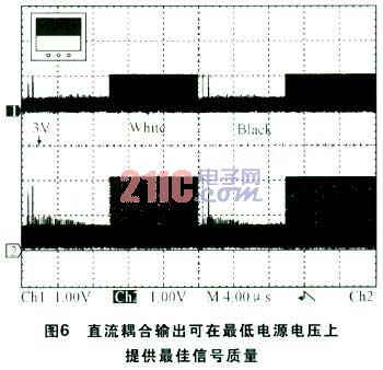
The DC-coupled output configuration also provides optimum video performance, as shown in Figure 6, where there is no line or field tilt, allowing the lowest supply voltage to be used. In this mode, the OPA360 provides excellent video fidelity at source voltages as low as 2.8V with no signal clipping. The disadvantage of DC-coupled output is that the supply current in its operating mode is slightly higher, but the quiescent current is the same in shutdown (sleep) mode.
Conclusion In order to successfully design a high-performance video system into a portable application, careful consideration must be given to the details, and the integrated solution is significantly better than a discrete solution with low supply voltage and limited package size. Power consumption, especially for power-down modules, is critical to extending battery life. Finally, in-line coupled outputs can be used to achieve the lowest cost, highest performance, and smallest overall size decision, while integration features and best design are strong. The powerful combination makes TI's OPA360 amplifier ideal for the design of TV output functions for camera phones.
The Church Led Display also need to keep up with the times, introduction of new technologies, Church Led Display can provide believers with more convenient gathering and prayer information,Church Led Display also can add some solemn and pious effect , and for the church wedding to create a romantic warm atmosphere; Shenzhen Cxcolor optoelectronics Co.,ltd is professional produce LED display, LED stage rental screen, advertising LED display, small spacing LED display, led transparent screen, car Led Screen, led ball screen, Church Led Display,led energy-saving screen, etc., to supply customers a complete set of LED display solutions.

Church Led Display
Church Led Display,Hd Church Led Display,Church Rental Led Displays,Church Digital Display
Shenzhen Cxcolor Optoelectronics Co., LTD. , http://www.largeledscreen.com