1 Introduction With the continuous development of automotive electronics technology, more and more electronic devices are on the vehicle, and together with sensors and actuators, many complex electronic control systems are formed. As a result, the electronic circuits connecting these electronic devices rapidly expand, wiring becomes more and more difficult, resulting in a significant increase in the weight of the vehicle body and a decrease in the reliability of the vehicle operation. The traditional point-to-point connection method can no longer meet the requirements of the development of modern automotive electronics technology, and the multiplexed vehicle network technology has become an inevitable choice to solve these problems. The control area network CAN (Controller Area Network) introduced by Germany's BOSCH company [1] has been widely used in automotive internal networks due to its stable performance, low price and high reliability and real-time. The adoption of the CAN bus makes the sharing of information and data inside the car a reality. However, the sharing of information data is now not limited to the interior of the car, and many data information needs to be exchanged with the outside world. This information is mainly used in car navigation, car GPS positioning, car anti-theft, car remote monitoring, car remote scheduling and charging. Due to the characteristics of vehicle mobility, many information that interacts with the outside world needs to be transmitted wirelessly. Therefore, we choose GPRS (General Packet Radio Service) with wide coverage, fast access speed, and flow metering. Carry wireless data communication. GPRS is a wireless packet switching technology developed on the basis of GSM [2], called 2.5G, with a maximum bandwidth of 171.2Kb/s, which can better meet the requirements of wireless communication.
2 Overall network topology The overall network topology is shown in Figure 1. The electronic control unit inside the car is connected to the CAN network. The internal data of the car is transmitted through the CAN bus, while the data that needs to interact with the outside world is transmitted via CAN/GPRS. The car gateway sends and receives. 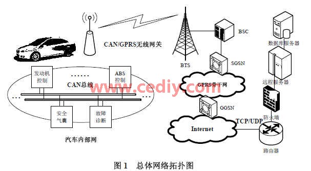
This article refers to the address: http://
The data enters the GPRS backbone network through the base transceiver station BTS (Base Transceiver Station), the base station controller BSC (Base Station Controller) and the GPRS service support node SGSN (Serving GPRS Support Node); then the GPRS gateway support node GGSN (Gateway GPRS) Support Node), access to the Internet Internet; and can transfer data to the Internet remote server via TCP or UDP protocol.
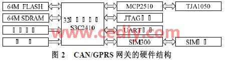
3 CAN / GPRS wireless car gateway hardware implementation Because the entire car internal CAN network and the external interaction data need to send and receive through the CAN / GPRS wireless car gateway, so the gateway needs to be equipped with a higher performance microprocessor. We chose a Samsung 32-bit ARM9 microprocessor S3C2410X with a high price/performance ratio as the main controller of the gateway. The S3C2410X includes the ARM920T core with a maximum processing speed of 203MHz [6]. The rich peripherals include a 3-channel UART, a 4-channel DMA, two SPI interfaces, 117 general-purpose I/O ports, and 24 external interrupt sources. A Samsung K9F1208 NAND Flash chip (64M *8Bit) is used to store the bootloader, Linux kernel, root file system and gateway program of the gateway software system. Two HYNIX HY57V561620 DRAM chips (4Banks*4M*16Bit) form 64M SDRAM for loading the Linux operating system and running programs. A 12MHz active crystal is used. A 20-pin JTAG interface was designed to program the bootloader. Use one MAX3232 to form the UART debug interface. Since the input voltage of the entire system is 5V, it is necessary to use the AMS1117-3.3 and AMS1117-1.8 to obtain stable 3.3V and 1.8V voltages, respectively.
The CAN controller selects Microchip's MCP2510, and the CAN transceiver selects Philips' TJA1050 to form the gateway's CAN communication module. The MCP2510 supports CAN bus V2.0A and V2.0B specifications with a communication rate of up to 1Mb/s, three transmit buffers, two receive buffers, and a high-speed SPI interface supporting 0,0 and 1,1SPI modes. The TJA1050 has the ability to transmit and receive bus differential signals and to resist transient interference in automotive environments. The GPRS interface of the gateway uses SIMCOM's SIM300 GSM/GPRS module, which provides wireless interfaces for services such as GSM voice, short message and GPRS Internet access. Use a 6-pin SIM card holder to connect to the SIM card. The hardware structure of the gateway is shown in Figure 2.
The S3C2410's SPI interface is directly connected to the MCP2510's SPI interface during actual hardware connections. The TXCAN and RXCAN pins of the MCP2510 are connected to the TXD and RXD pins of the TJA1050, respectively, and the CANH and CANL pins of the TJA1050 are connected to the CANH line and CANL line of the CAN bus, respectively. Because the S3C2410's UART port does not lead to DCD, DTR, DSR, and RI signal pins, it is best to use all the signal pins through the SIM300 wireless networking. Therefore, we use the PHILIPS SC16C550 to extend the standard UART interface from the S3C2410.
The SIM300's UART interface is connected. The hardware circuit schematic of the main communication module of CAN/GPRS gateway is shown in Figure 3. 
4 CAN/GPRS wireless car gateway software implementation
4.1 ARM-Linux operating system porting.
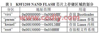
VIVI developed by MIZI of Korea is used as the bootloader, ARM-Linux with 2.6 kernel is selected as the embedded operating system, and Linux root file system is made with busybox. The storage area on the K9F1208 NAND Flash chip is divided as shown in Table 1.
4.2 ARM-Linux SPI driver programming uses the S3C2410's own SPI channel 0 to communicate with the MCP2510. The SPI driver flow [3] is as follows:
(1) Write the SPPRE0 register to set the baud rate.
(2) Write the SPCON0 register to set the data transfer to 0,0SPI mode.
(3) Write 0xFF 10 times to the SPIDAT0 register to initialize the MCP2510.
(4) Set the GPIO pin to be used as a chip select and set low to activate the MCP2510.
(5) Check if the transmission status bit REDY of the SPSTA0 register is 1, and if so, write data to the SPTDAT0 register and send it out.
(6) If the TAGD of the SPCON0 register is not enabled, write 0xFF to the SPTDAT0 register. After confirming that REDY is valid, the data can be read from the SPRDAT0 register. After the TAGD is enabled, the data can be read from the SPRDAT0 register after confirming the REDY.
(7) Set the GPIO pin, the signal is set to high level, and the chip select is not enabled.
4.3 CAN driver writing under ARM-Linux Because the CAN application layer protocol is designed based on the CAN2.0B technical specification, the communication message uses the CAN2.0B extended frame format.
Initialization: (1) send 0xc0 reset command, MCP2510 reset; (2) enter configuration mode, set CAN bus baud rate, turn off interrupt; (3) set mask register RXM (0, 1) SID (L/H), RXM (0, 1) EID (8/0) and filter register RXF (0 ~ 5) SID (L / H), RXF (0, 1) EID (8 / 0) and start; (4) set the CAN device to be ordinary Mode and switch to normal mode; (5) clear the receive and transmit buffers. (6) Turn on the receiving or sending buffer and turn on the interrupt. Send message: (1) Write identifier register TXB (0~2) SID (L/H), TXB (0~2) EID (8/0); (2) Send buffer data length register TXB (0) ~2) DLC writes the length of the message to be sent; (3) When writing data, it needs to send 0x02 write command to the MCP2510, send the buffer data register TXB (0~2) DM 8-bit address code and need to send Message data; (4) Transmit validity check must be performed, that is, the TXREQ bit of the transmit buffer control register TXB (0 to 2) CTRL is detected. When it is 1, it indicates that the message is being sent, and it has to wait; when the message is sent, the bit will be automatically cleared, and then the next message data to be sent can be written. Receive message: (1) Send 0xA0 status read command to MCP2510, and continuously detect interrupt flag register CANINTF. When RX(0,1)IF bit is found to be 1, it indicates that the receive buffer has received the message; (2) The ID of the frame can be read from the receive buffer identifier register, and the length of the received message can be read from the receive buffer data length register RX(0, 1) BDLC; (3) when reading the data, it must be sequentially sent to the MCP2510. The MCP2510 will send the data through the SO pin after transmitting the 0x03 read command and receiving the 8-bit address code of the buffer data register RXB(0,1)DM. After reading the data, the RX(0,1)IF bit needs to be cleared.
4.4 ARM-Linux serial port driver modification and loading Because we are using the UART controller chip SC16C550 compatible with the 16c550 register, we need to load its driver serial_8250.c under Linux. However, the SC16C550 chip is connected to the S3C2410 microprocessor through the external bus. Therefore, the driver's serial8250_isa_init_ports function needs to be added to the bank space of the SC16C550 chip, including setting the read/write timing, speed and bus width. [4] .
4.5 GPRS networking under ARM-Linux
GPRS completes networking through PPP (Point-to-Point Protocol). PPP is a solution for creating and running IP Internet Protocol or other network protocols over a directly connected serial link. Support for PPP under ARM-Linux requires kernel and application management. For the Linux 2.6 kernel, you need to choose PPP support when configuring the kernel. For example, under the Network device support menu, select Support PPP, PPP Asynchronous/Synchronous Serial Communication, and PPP Compression. In addition, you need to transplant the PPP application toolkit under Linux, that is, add the pppd and chat programs obtained after cross-compilation to the root file system. In the /etc/ppp directory of the root file system, you also need to write three script files: options (pppd configuration script), gprs-connect (pppd connection script), gprs-disconnect (pppd disconnect script). In the options script, you need to specify the serial console device /dev/ttse/0, the connection baud rate 115200, the connection and disconnect script storage path; run the chat program in the gprs-connect script, and specify the APN access point, such as : 'AT+CGDCONT=1,"IP","CMNET","",0,0' and ISP call number: 'ATD*99***1#' and so on. After the system is started, the GPRS wireless access to the Internet can be realized by directly using the pppd & command.
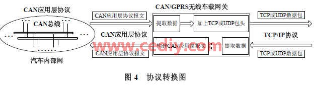
4.6 CAN application layer protocol and UDP or TCP protocol conversion Because the GPRS network is based on the TCP/IP protocol, the GPRS or TCP protocol can be used to communicate with the Internet remote server via the GPRS network. Since the S3C2410 not only ported the Arm-Linux operating system, it already supports the TCP/IP protocol itself, and we also loaded the CAN application layer protocol. Therefore, when sending data wirelessly on the gateway, you only need to add the UDP or TCP header to the data in the CAN packet data field on the car CAN network. When receiving data wirelessly on the gateway, just remove the UDP or TCP. The header of the packet, the obtained data can be sent to the CAN network in accordance with the message format of the CAN application layer protocol. The protocol conversion is shown in Figure 4.
4.7 Implementation of the Heartbeat Program Because the CAN/GPRS wireless gateway communicates with the Internet remote server, abnormal connection may occur. Therefore, a heartbeat program is needed to detect the occurrence of abnormal conditions and redial through the heartbeat program to ensure the wireless communication link. Normal connection [5]. We can ping the remote server regularly. If the ping is successful, the wireless communication link works normally. If it fails to ping multiple times, it must disconnect and redial.
5 Conclusions This paper introduces the implementation of CAN/GPRS wireless vehicle gateway in detail. The implemented gateway can better complete the interaction between the internal CAN network data information and the outside world in the experimental communication network, and it can run stably for a long time. Achieved the job requirements.
The author of this paper is innovative: the ARM-Linux embedded operating system, heartbeat program and underlying hardware driver can be successfully run on the CAN/GPRS wireless vehicle gateway, and the conversion of the CAN application layer protocol and the TCP or UDP protocol is completed, which makes the interior of the car The CAN network can communicate wirelessly with the outside world.
RAM for LG G4,CPU for LG G4,Flex Cable for LG
Keco Technology Co., Ltd. , http://www.gdphoneparts.com