1 Phosphor degradation performance at higher temperatures
There seems to be no relevant information on the relationship between the excitation efficiency of phosphors for LEDs and temperature. However, there are sufficient facts to prove that the temperature rise does affect the performance and life of the phosphor.
Fluorescent powder manufacturers have tested that at 60 °C, the phosphor's excitation efficiency is reduced by 2%, and it is restored after cooling. And this is just a test for a short time. It has been shown that the temperature rises and the performance of the phosphor decreases. As for the unrecoverable performance degradation, it is a cumulative process that takes a certain amount of time.
We also often encounter such things, use or aging for white LEDs for a while, and find that the LEDs are brighter, see Figure 1. At present, this situation occurs for low-power LEDs within 1000 hours (here, the 1000-hour luminous flux may be greater than the initial value, and the product and patch products in the middle of 2008 may be close to or reach 1000 hours). For low power packaged LEDs, this condition can be maintained for up to 2000 hours. This condition may result from the following:
A: The effect of the phosphor and the mixed gel reduces the performance of the phosphor, and restores the performance of the phosphor under the initial action of the temperature;
B: Phosphor and mixed gel action to improve the performance of the phosphor.
C: The performance of the Blu-ray chip is enhanced for the initial period of time.
It was found in the experiment that during the initial period of time, the luminous flux of the white LED rises from the beginning and falls from the beginning. This situation also occurs when the same red chip is packaged in different manufacturers. Therefore, it is difficult to determine whether it is a problem of phosphors or a problem of packaging materials and packaging processes in only a short period of time.
However, in the life test of low-power blue LEDs, it is found that there is a phenomenon that the luminous flux rises in the initial period of time, and the general luminous flux rises in about 200 hours. The luminous flux of the plug-in white light is generally about 100 hours. It can also be inferred that the white LED should be the first degradation of the performance of the phosphor.
After the short-lived light flux boost period of the low-power white LED, the situation is not optimistic. Starting with an airplane without wings, the result will be self-evident. High-power white LEDs generally have a luminous flux increase of about 100 hours, and then are not stable until 6000 hours. Over time, the luminous flux of some products has a large rise and fall. After 6,000 hours, it basically began to steadily slide down all the way. At present, the general high-power white light products reach the end of life (50% of light decay) in 1.5~20,000 hours.
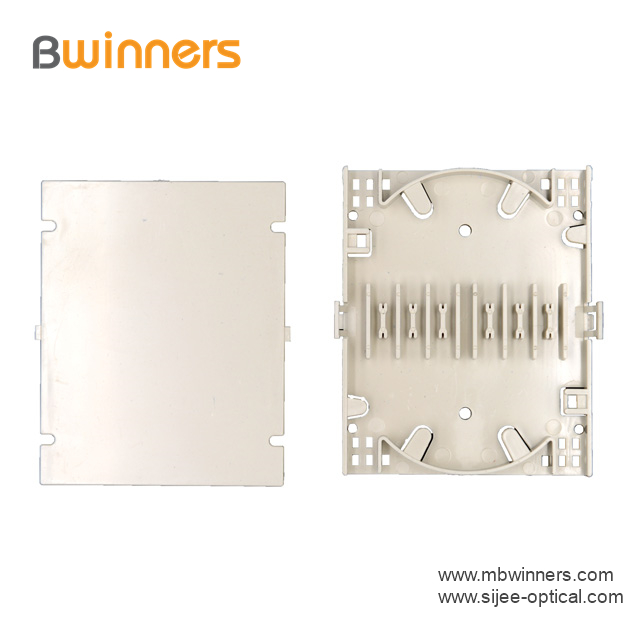
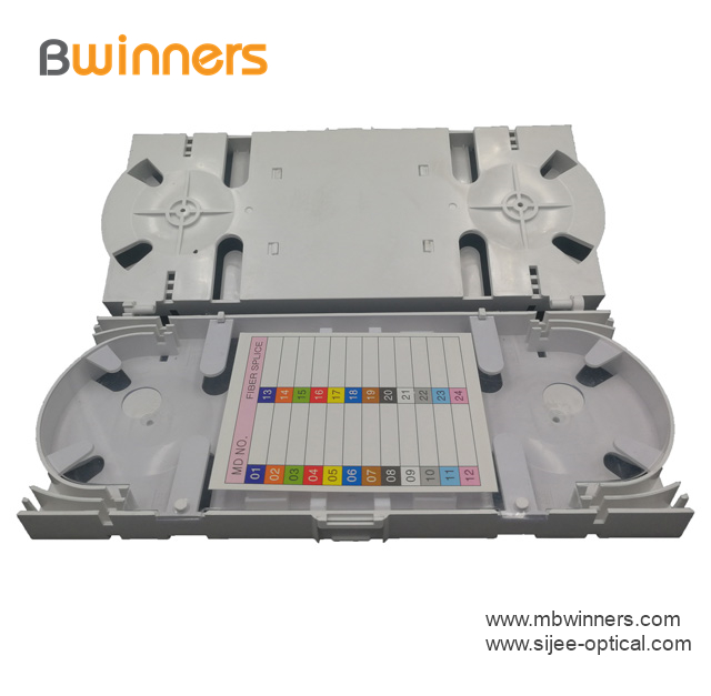
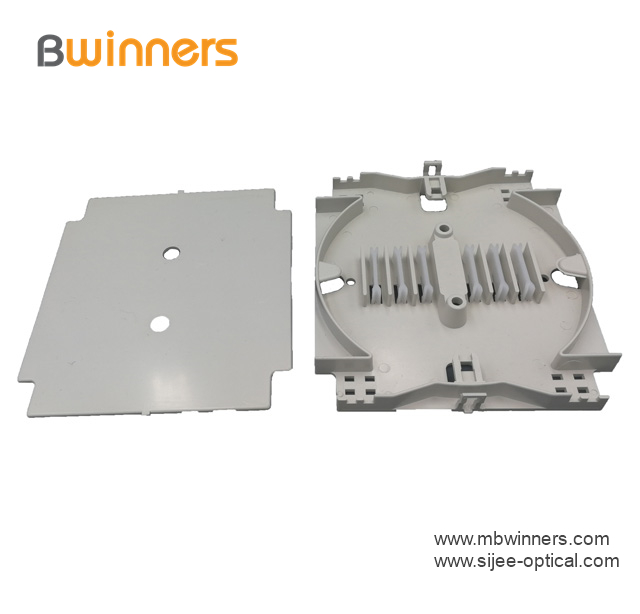
FTTH Fiber Optic Splice Tray is designed to provide a place to store the fiber cables and splices and prevent them from becoming damaged or being misplaced. It is also called a splice enclosure or splice organizer. This device does not contain any technical functions, and the design is simple. Also, Fiber Optic Tray has a very low price for people to afford. However, the importance of fiber splice tray for protecting fibers is significant. And the skills needed for using a fiber splice tray is not as simple as you think.
Made by industrial high-quality ABS plastic, Fiber Optic Cable Tray is provided to place the fiber splice points and pre-terminated for fiber connectivity. The splice tray expands fiber splice capabilities as well as provides the splicing location for fiber optic cables. It can be put into the fiber distribution frame, fiber splice closure, optic terminal box, etc. Sijee offers different shapes of fiber splice tray with or without termination function. Fiber Optic Tray, Fusion Splice Box, Fiber Optic Cable Tray, Splice Tray Optic Fiber are available.
Applications:
Fiber splice trays are usually placed in the middle of a route where cables are required to be joined or at the termination and patch panel points at the end of the cable runs. Also, splices can be placed in a splice tray which is then placed inside a splice closure for OSP (outside plant) installations or a patch panel box for premises applications. As for indoor application, fiber splice trays are often integrated into patch panels to provide for connections to the fibers.


FTTH Fiber Optic Splice Tray
Fiber Optic Tray,Fusion Splice Box,Fiber Optic Cable Tray,Splice Tray Optic Fiber
Sijee Optical Communication Technology Co.,Ltd , https://www.sijee-optical.com