A typical metal detector is composed of two main components: the detection unit and an automatic rejection system, with the detector being the key part. Inside the detector, there are three sets of coils: a central transmitting coil and two identical receiving coils. The oscillator connected to the transmitting coil generates a high-frequency alternating magnetic field. In the absence of any interference, the receiving coils produce equal induced voltages, which cancel each other out, maintaining a balanced state.
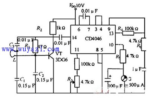
The circuit formed by VT, C1, C2, and the probe L creates an oscillator operating at approximately 300 kHz. The probe uses a large coil with a diameter of 440 mm. When this coil comes close to a metal object buried underground, the metal acts like a short-circuit loop, reducing the inductance of L and increasing the oscillation frequency. This change alters the deflection of the meter needle, which is typically designed as a zero indicator, with the center of the dial representing the neutral position. This type of circuit is essentially a frequency-to-voltage converter.
When a metal impurity enters the magnetic field, it disrupts the balance. The induced voltages from the two receiving coils can no longer cancel each other out. The resulting unbalanced voltage is amplified by the control system, generating an alarm signal that indicates the presence of metal contaminants. This signal can then be used to activate an automatic rejection device, removing the unwanted material from the production line.
The image below shows a schematic diagram of a metal detector built using the CD4046 IC.
Thunderbolt 3 Cables,Thunderbolt 3 Cable,Fast Charging Thunderbolt 3 Cables,Usb C To Type-C Data Cable
Dongguan Pinji Electronic Technology Limited , https://www.iquaxusb4cable.com