PWM control is one of the simplest methods available, especially when dealing with systems that operate at 48V or 96V. However, it's important to note that the open-circuit voltage of a solar panel can easily exceed 200V DC. To ensure system reliability, it's necessary to provide a separate auxiliary power supply for both the CPU and the driver circuit. This design allows for a charging current range of 50 to 100A, which is manageable with this approach.
The low power loss on the MOSFETs in a PWM system means that only a small heatsink is required to keep the components cool. This makes the overall design more compact and efficient. The following images show the physical layout of the board:
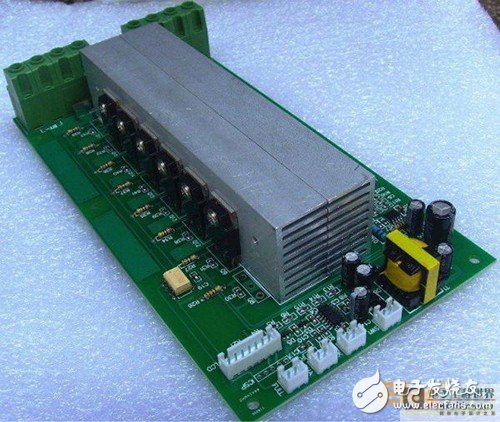
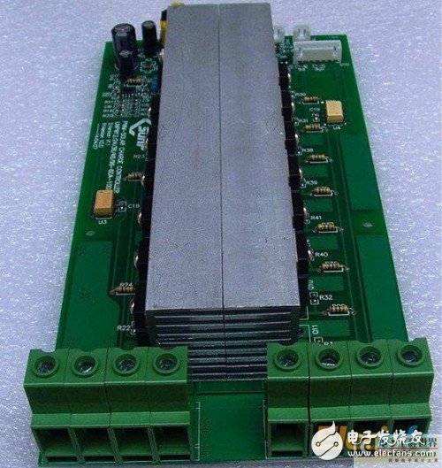
In essence, the PWM control method works by switching a group of MOSFETs, much like a relay. During the evening, these MOSFETs are turned off to prevent reverse current flow from the battery back to the solar panel. I used the TLP250 optocoupler for driving the MOSFETs, which helps isolate the control circuit from the high-voltage side.
One of the key advantages of this setup is that it doesn't require a fan for cooling. Instead, a heatsink is used to conduct heat away from the MOSFETs, eliminating the need for air cooling. The switching frequency of the MOSFETs is very low—under 1kHz—which further reduces power losses and simplifies the design.
The system uses a microcontroller to generate PWM signals, and the battery voltage is continuously sampled to perform a PI (proportional-integral) adjustment. This ensures stable and efficient charging. Notably, the duty cycle can go up to 100%, as the driver is powered separately from the main power supply. At 100% duty cycle, the MOSFET effectively acts as a direct connection between the solar panel and the battery, allowing maximum energy transfer without any losses.
Wonke Electric CO.,Ltd. , https://www.wkdq-electric.com