The diversification of electronic products puts new demands on storage-related technologies, including lower costs and security. Lattice Semiconductor’s LatticeXP device, for example, combines a low-cost FPGA fabric with non-volatile, infinitely reconfigurable ispXP technology for instantaneous power-up and single-chip applications with excellent security .
LatticeXP devices use ispXP (eXpanded Programmability, extended programmability) technology that combines SRAM and non-volatile flash memory to enable FPGAs to be both non-volatile and infinitely reconfigurable. Non-volatile, infinitely reconfigurable FPGAs, along with their instantaneous power-on operational performance and secure single-chip solutions, represent the “home of hope†in the FPGA world. With such an FPGA, the user can simultaneously obtain the numerous advantages of infinite reconfigurability and non-volatile of SRAM.
LatticeXP devices are implemented by a cost-effective, low-k, 130-nm CMOS flash memory process using copper plating. The process was jointly developed by Fujitsu Limited and Lattice Semiconductor. LatticeXP devices support 1.2V, 1.8V, 2.5V, and 3.3V supply voltages. The chip size is more than 80% lower than Lattice's past non-volatile FPGAs.
SRAM-based memory cells control the operation of the device logic. These cells are loaded from on-chip flash memory within 1 millisecond of power-up, providing instantaneous power-up capability, or booting with user commands. The device can also be configured via a microprocessor interface, the sysCONFIGTM interface or the JTAG interface. Unlike traditional SRAM-based FPGAs, LatticeXP devices do not require an external boot memory, so they provide a single-chip solution that reduces the board area and simplifies the system manufacturing process. Since there is no external boot device, there is no need for external programming signal flow at startup, and snooping external programming signal flow is the main security risk of SRAM FPGA. LatticeXP also prohibits readback of the programming signal stream from the SRAM and flash portions of the device, further increasing device security.
Lattice XP Structural Features
The main features of the LatticeXP device structure are as follows:
â—† Based on an easy-to-integrate industry-standard four-input lookup table (LUT) logic block.
â—† Only 25% of logical blocks contain distributed memory. This optimization not only meets the needs of most users for a small amount of distributed memory, but also reduces costs.
â—† Since the device has a sysCLOCKTM phase-locked loop (PLL) and embedded module RAM (EBR), users can integrate these functions into the FPGA, eliminating the need for discrete components and further reducing costs.
â—† Advanced sysI/O buffers can support LVCMOS, LVDS, LVTTL, PCI, and SSTL and HSTL standards, making it easy to connect with industry-standard bus standards easily and efficiently. Lattice has carefully selected these standards to greatly expand the application range and reduce the chip area.
â—† LatticeXP devices have circuits specifically designed to simplify the DDR memory interface, providing high performance, integration, signal integrity, and ease of design features for these FPGAs. DDR memory is a low-cost memory: Estimates show that DDR accounted for 75% of the DRAM market in 2004, an increase of 39% over 2002.
LatticeXP device device is a logic block array in the middle, surrounded by programmable I / O cells (Program I / O Cell, referred to as PIC). Embedded blocks of RAM (sysMEM Embedded Block RAM, abbreviated as EBR) are distributed between the rows of logic blocks.
There are non-volatile memory blocks on the left and right sides of the PFU array. In configuration mode, non-volatile memory blocks are programmed through the IEEE 1149.1 interface or the sysCONFIG external interface. At power-up, configuration data is transferred from the non-volatile memory block to the configuration SRAM. With this technology, there is no longer any need for expensive external configuration memory and the risk of unauthorized readbacks. Data is transferred from the configuration data through the wide bus from the non-volatile memory block to the configuration SRAM. This process takes only a few milliseconds, providing instantaneous power-on capabilities that can easily interface with many applications.
There are two kinds of logic blocks in the device: Programmable Function Unit (PFU); Programmable Function Unit without RAM (PFF). The PFU contains building blocks for logic, algorithms, RAM/ROM, and registers. PFF contains building blocks for logic, algorithms, and ROM. The optimized PFU and PFF can realize complex design flexibly and effectively. Each type of building block in the device has one row of PFU for every three lines of PFF.
Each PIC block contains two PIO pairs with sysIO interfaces. The PIO pairs on the left and right sides of the device can be configured as LVDS transmit and receive pairs. The sysMEM EBR is a large dedicated flash memory block that can be configured as RAM or ROM.
The PFU, PFF, PIC, and EBR blocks are distributed in rows and columns in a two-dimensional grid, as shown in Figure 1. These blocks are connected to horizontal and vertical routing resources. The layout and routing functions of the software will automatically allocate these routing resources.
The system clock phase-locked loop (PLL) has frequency multiplication, division, and shift functions at the end of the system memory block row. It is used to manage the phase relationship of the clock and each LatticeXP device provides up to four PLLs.
Each device in this series comes with an internal logic analyzer (ispTRACY) JTAG port. The system configuration port allows serial or parallel device configuration. LatticeXP devices can operate at 3.3V, 2.5V, 1.8V, and 1.2V and are easy to integrate into the entire system.
PFU and PFF are the core of the device
The core of LatticeXP device is PFU and PFF. The PFU can be programmed to implement logic, algorithms, distributed RAM, and distributed ROM functions. PFF can be programmed to implement logic, algorithms, and ROM functions. Unless otherwise specified, each PFU consists of 4 interconnected slices. All interconnections with the PFU come from the wiring area. Each PFU has 53 inputs and 25 outputs.
All LatticeXP devices contain two ports for device configuration and programming. The test access port (TAP) supports bit width configuration, while the sysCONFIG port supports both byte width and serial configuration.
Nonvolatile memory in ispXP can be configured in three different modes:
â—† Configured via the sysCONFIG port in sysCONFIG mode. Note that this method can be configured while the device is working. â—† Configured in port 1532 mode via port 1149.1 â—† Configured in background mode through port 1149.1. When reprogramming in this mode, the device can work at the same time
The SRAM in LatticeXP can be configured in four different modes:
â—† Configured by on-chip non-volatile memory at power-on â—† Configured by a user-issued refresh command. Note that this configuration can be achieved by toggling the level of the PROGRAMN pin or sending a command via the JTAG port in 1532 mode â—† Configuration via port 1149.1 in 1532 mode â—† Configuration via the sysCONFIG port in sysCONFIG mode
At power-up, the SRAM of the FPGA is configured with the sysCONFIG port. After power-up, the IEEE 1149.1 serial mode can be activated at any time by sending the appropriate command via the TAP port. Once a certain configuration port is selected, the port is locked and the other configuration port cannot be activated until the next power up.
Main attack PC and consumer products market
DDR memory was originally a high-performance, low-cost memory solution used primarily in personal computers and other cost-sensitive consumer manufacturing markets. Recently, non-consumer products have also begun to adopt DDR memory due to the economic pressure imposed on the entire electronics industry. DDR is a SDRAM-based memory technology. DDR SDRAM access speed is twice that of SDRAM because DDR data transfer occurs on all two edges of the clock.
When trying to implement a high-speed DDR interface in an FPGA, designers often find it difficult. These difficulties come not from functional issues but from the natural result of dealing with data windows in the order of signal propagation speeds in FR4 and FPGA wiring. The different logic speeds caused by the process, temperature, and voltage make these timing requirements more complex.
Compared with the common clock signal, the control and preprocessing of the strobe signal are needed to further complicate the implementation of the DDR design. These challenges include the alignment of data (DQ) and data strobe signals (DQS). The two edges of the clock signal separate one data stream into multiple data streams and manage data transfer from the DQS clock domain to the system clock domain. However, LatticeXP FPGAs provide engineered solutions. It greatly simplifies the designer's work.
LatticeXP provides dedicated resources for aligning DQ and DQS signals, multiplexing double data rates, and transferring data from the DQS clock domain to the system clock domain. The DQS delay block receives the edge-aligned DQS signal from memory and phase shifts it by 90 degrees. This phase-shifted DQS signal can now be used by the FPGA input register to capture and demultiplex rising and falling edge data. Note that the register that captures rising edge data is a falling edge trigger. This half clock transfer register uses the falling edge of DQS to transfer rising edge data from the first register so that the rising and falling edge portions of the data are now sent to the next stage register with the same falling edge of DQS.
As FPGA devices continue to evolve, making electronic products more likely to appear, engineers can use these new devices to develop cost-effective designs and create a more colorful world.
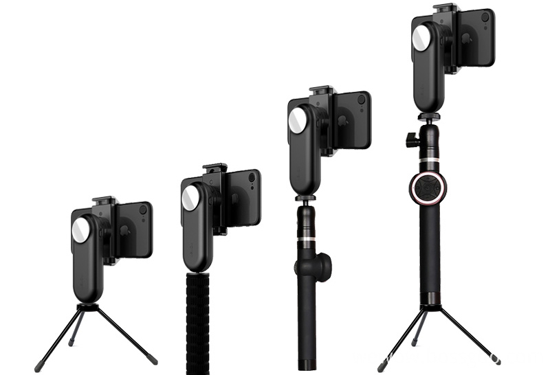
Single-Axis Stabilizer is a pivoted support that allows the phone or Gopro staying stabilized. With a gyro-stabilized gimbal system, it keeps stabilized or steerable horizon with automatic calibration to give you an unprecedented smooth shooting experience.

With the 1/4" Screw Adapter at the bottom, these handheld gimbal stabilizer can be matched with multiple filming accessories.

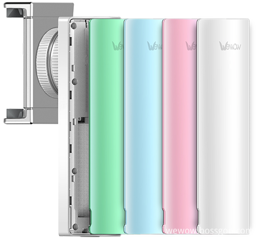
Smartphone Gimbal are designed as pocket size, portable and easy to take. You can carry it as easy as smartphone!

Wewow focusing on handheld stabilizer is a technology company which does R & D independently. With Wenpod series product released, the company achieved the industry's praise and quickly became the leader of the smart stabilizer industry.
Our service
1. Reply to you within 24 hours.
2. Already sample: within 1-2days.
3. Shipping date: within 24 hours once get the payment.
4. 12 months warranty.
5. After-sales service, solve within 3 working dates.
If you have any questions, please contact with us directly.
Wewow appreciates domestic and international business relationship!
Single-Axis Stabilizer,Professional Single-Axis Stabilizer,Single-Axis Stabilizer Kit,Stabilizer With Single Handheld
GUANGZHOU WEWOW ELECTRONIC CO., LTD. , https://www.stabilizers.pl