The lifetime of an LED is inversely proportional to the temperature of its PN junction. In some high-power LED lamps with limited space, reducing the temperature rise of the LED cannot be achieved by using a larger heat sink. For example, track lights, using a DC fan to force heat dissipation has become a last resort. In recent years, with the continuous improvement of manufacturing processes, the life of electric fans has been extended. Some manufacturers even claim that the life of electric fans is longer than that of LEDs. But in any case, the electric fan relying on mechanical contact is always unreliable for use in high-power LED lamps with high reliability requirements. An electric fan operation status monitoring circuit is added to automatically cut off the main circuit when the fan fails , To protect the LED from overheating damage, this idea can be evaluated. Based on this idea, a circuit for cooling fan detection was developed. The block diagram is as follows:
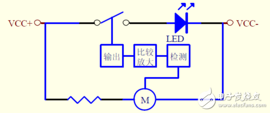
The principle of this idea is explained below
The main failure modes of fans are open circuit and locked rotor.
First look at the waveform when the fan is working:
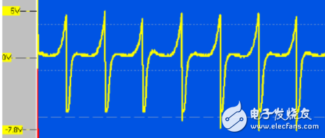
It can be seen that the waveform of the fan operation is a series of alternating waveforms, and a DC voltage value is output after capacitive coupling rectification and filtering. According to the presence or absence of this voltage, it can be distinguished whether the fan is working normally.
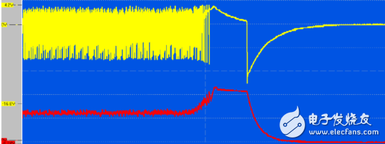
The waveform transition of the fan from normal operation to blocked rotation is shown in the figure below. The yellow waveform in the figure is the fan waveform, and the red waveform is the DC voltage waveform after capacitive coupling rectification and filtering. This DC voltage value has a voltage difference of more than 3 volts. When this voltage difference is added to the input of the comparator, an amplified signal can be obtained at the output of the comparator to control the opening and closing of the electronic switch.
There is no alternating waveform output when the fan is open, and the DC voltage after coupling rectification and filtering is zero. The above analysis is also applicable.
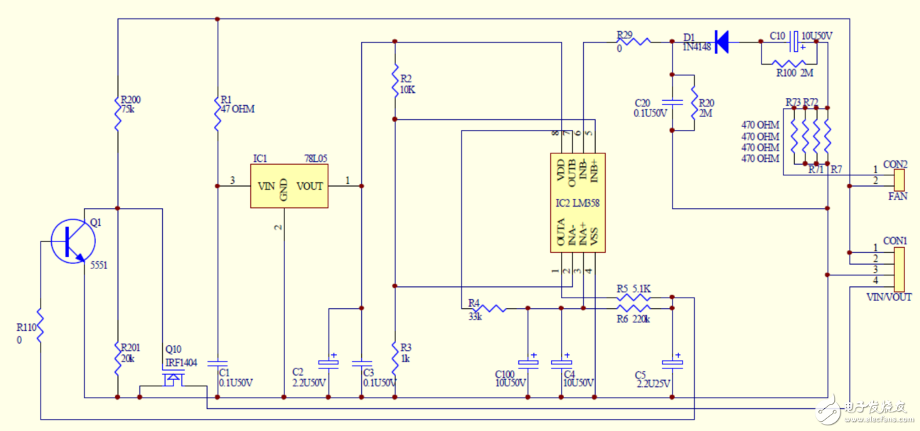
The actual schematic diagram is shown below. The 1-3PIN of CON1 in the picture is the 36V DC output terminal of the LED constant current driver, 2-4 is connected to the anode and cathode of the LED. Connect CON2 to a 24V 1.5W DC electric fan. LED selects 10 series and 10 parallel 50W light source. If the light source parameters of the driving power box are different, you can change the values ​​of R7 and R71-R73 in the figure, and select the appropriate electric fan.
The PCB diagram and the physical objects are as follows:
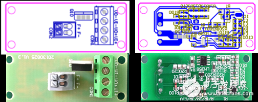
The switch tube in this case selects the MOSFET IRF1404 with VSS = 40V RDS (ON) = 0.004 Euro ID = 162A, which is used to control the 3.3A100W LED, and can work continuously for a long time without a heat sink. If you use a higher power LED, consider using a higher specification MOS tube, or install a heat sink on the MOS tube.
Features
â—† Designed For Water and Dust Tight(IP67)
â—† Small Compact Sizeâ—† UL&ENEC&CQC Safety Approvals
â—† Long life & high reliability
â—† Variety of Levers
â—† Wide Range of wiring Terminals
â—† Wide used in Automotive Electronics,Appliance and Industrial Control etc.
â—† Customized Designs
Dustproof Micro Switch,Micro Switch Company,Long Lever Micro Switch,Micro Selector Switch
Ningbo Jialin Electronics Co.,Ltd , https://www.donghai-switch.com