All adjustments are based on the correct cabinet design! Since the inverter box and -12dB crossover are more common, let's talk about the inverter box first.
Three elements of adjustment:
1) Adjustment of speaker resonance frequency.
2) Adjustment of the crossover frequency of the crossover.
3) Adjustment of the Q value of the crossover (low pass and high pass).
Purpose of adjustment:
1) The impedance harmonic peak of the speaker is suppressed by the speaker, so that the bass distortion is minimal and the sound quality is pure.
2) The attenuation crossover point of the crossover falls on the correct crossover point. (As for whether it is -3dB or -6dB crossover, we can understand the basic ability to continue the discussion)
3) By adding impedance compensation to the speaker, the Q value of the crossover is close to the ideal crossover curve, and the resolution and clarity of the playback are improved.
In general, the three-point accuracy achieves the goal, and the sound quality is guaranteed. The rest of the adjustment items are built on this basis. And most of them are determined by the nature of the unit.
Please prepare the following stuff:
1] Hugo Fever Disc (1). {(My disc)} with trumpet flowers is better.
2) A multimeter.
3) 1K / 1W resistor.
4) A piece of graph paper.
1) Adjustment of speaker resonance frequency.
Install the high and low speakers and crossovers into the cabinet (because they all occupy the volume of the cabinet). The crossovers and trebles do not need to be wired. Directly connect the bass unit to the power amplifier through the speaker terminal, and put a small song on the boot. Adjust the volume to the volume you usually like. Pay attention to the time of the potentiometer. (There will be adjustments of the amplifier and the speaker in the future, which is the so-called collocation. There will be time to write this article to discuss this section.) Measure the voltage, (I think everyone has a digital multimeter, it doesn't matter if the pointer is the same.). Note: Volume is also a function of sound quality.
Ok, now, connect a 1K resistor (in order to isolate the internal resistance of the power amplifier) ​​into one of the terminals, connect the multimeter to the speaker terminal, put the Hugo 400H-1K audio signal, see what the multimeter voltage is, fine-tune the volume The potentiometer makes the indication value an integer, (if the voltage value is too small, the resistance value can be reduced, it can be from 20 ohms to 1K, but the error is larger, strictly speaking, a millivolt meter is used).
Now, put the audio signal from 25H to 1K (more than 1K, we have to wait until the tuner is tuned), trace the points on the graph paper to make a graph, and an impedance curve comes out. Friends who have [My Disc] this CD can put the 10H-99H audio signal, but this is a frequency sweep, one Hz every 5 seconds, plotting points, drawing, the picture is comparable to the instrument.
We can see at a glance whether the speaker under test meets the design. A good design has two harmonic peaks (two peaks with a valley) and is symmetrical. Now the low point is called F1, the valley point is called F, and the high point Is called F2, and F / F1 = F2 / F (ah, ah, really, the more I say, the better the sound quality is with only one ratio, which we will discuss later).
But you may be disappointed:
[1] Maybe you only have one peak, that is to say that your speaker is a failed design, and you have to go all out. These are the two extremes-the box and the inverted hole are too large or too small.
[2] There are two peaks but they are not symmetrical. Well, there is salvation, we just want to make it symmetrical.
a) The front peak is large, the phase inversion hole is large, and the phase inversion tube is short.
b) The rear peak is large, the phase inversion hole is small, and the phase inversion tube is long.
Since the inversion hole is opened well, it is more difficult to change, so only the length of the inversion tube can be changed to make the two peaks symmetrical. Of course, it is also difficult for us to adjust the length to the right one at a time. There is a formula. I forgot the specific content. I have the opportunity to calculate it and post it again. Temporarily decrease or increase by 1 cm in length, and finally fine-tune when the sound-absorbing cotton is set, the sound-absorbing cotton will increase the volume.
The two peaks are symmetrical and our box is adjusted. After we adjust the crossover, we can use the sound-absorbing material to fine-tune the frequency projection of the speaker and the Q value of the speaker according to the characteristics of the speaker. Then use RMAA software to test the speakers, (computers have been popularized, and it is easier to have a fever today) to order more advanced materials.
One more question for everyone: why can a 6.5-inch speaker be used as a bookshelf box or a floor box?
Understand this, you will know that the optimal ratio of the function between the unit to the box volume, the area of ​​the inverted hole and the length of them is different from your pursuit.If they have an optimal value, you can catch (do) one Good speaker.
Extra words:
The main role played by a speaker is at low frequencies, and all parameters are functions, which is where the speaker is the most headache. At 100H up the frequency point, what kind of unit is exactly what kind of sound, we just let the unit work in the best state, at this time, the speaker index is the best and the distortion is the smallest, which is the final adjustment. purpose. Remember: adjustment can not change the unit, the human ear can hear 1% distortion, what is the marked distortion of the domestic unit?
The reason why there are no formulas cited in the scriptures is because we are not a subject researcher, nor a essay, and do n’t understand so much. Moreover, I was stunned by so many specious theories. I always wanted to say: Tell me how to do it! No, it's over.
Then talk about the "soul" of the speaker-the adjustment of the crossover.
Adjust the harmonic frequency of the speaker, I recommend you to make the two peaks symmetrical, and wait for the adjustment of each branch, and then adjust the total.) Adjust the crossover frequency of the crossover.
2) Adjust the crossover frequency of the crossover. ------ Note: The speaker and crossover have been shaped, and the crossover point has basically met the requirements of the unit, otherwise it will not be adjusted to the design.
(There are two design methods for crossovers: a) fixed impedance design. B) crossover impedance design.)
Now remove the woofer and the crossover, remove it with impedance compensation on the crossover, weld it according to the normal connection method, connect the amplifier, connect the power amplifier, the volume is the same as the first part of the test, keep the original time is several minutes Orientation, because the speaker is not needed at this time, the bass sound is short-circuited, and the hearing is no longer accurate. This is convenient and a lot of garbage. Anyone can easily connect the multimeter.
Connect the multimeter to the woofer terminal, measure the actual voltage value of the woofer, put the 1KH audio signal, and fine-tune the volume potentiometer to an integer. (At this time, for convenience, let ’s assume: for example, the multimeter indicates 3V. The crossover frequency of the crossover is for example 3.15K --- Hugo happens to have a frequency point of 3.15K.) Well, put the signal of 500H-12KH, draw the points on the graph paper to make a graph, this is a low-pass curve .
The multimeter is connected to the tweeter terminal, don't change the other! Put 1KH-20KH audio signals, as usual, this is the Qualcomm curve.
At this time, we can intuitively see the crossover point. It is the intersection of the two curves. We now only adjust the intersection point, and the rest will be ignored.
Ah, is it at the crossover point of our crossover? Is it according to the roll-off point we designed *?
Now there is a way to remedy the problem. I stare at you.
We originally assumed that the output is 3V, and the half power point of 3V is: 3 * 0.707 = 2.12V,
We only adjust the capacitance value, (of course assuming that the inductance is basically consistent) first let the low-pass 3.15K point fall exactly at 2.2V.
Then adjust the high-pass capacitor to make it just cross this point at 2.2V *.
In this way, the crossover point is adjusted.
Necessary explanation: The reason why no mathematical proof is added is for operability. The tedious mathematical derivation always makes people have: you do n’t say I still understand, the more you say I am more confused.
But briefly, you have to explain: 0.707 is a vector, and both units are divided into 0.707 times the voltage, and the combined power is exactly equal to the original input power. Readers will find that they are flat when measuring the frequency response synthesis curve in the future. Mathematical derivation is left to smart readers to complete.
Maybe the two curves are ugly, it doesn't matter, ah, the next step is our third step, Q value adjustment.
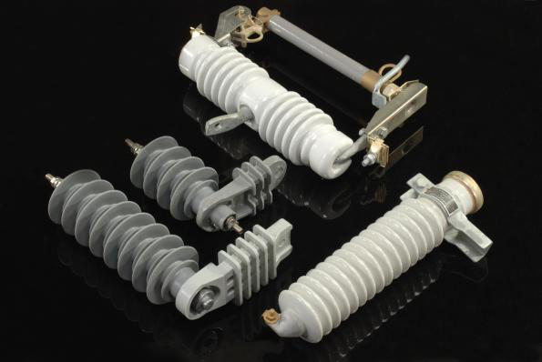
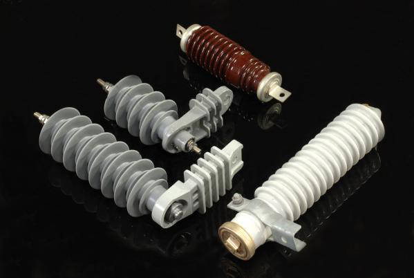
Cut Out Fuse is a combination of a fuse and a switch, it`s voltage is up to 11kv-33kv, which is made of porcelain, polymer or steel. When the current exceed the specified value, Drop Out Fuse ( Polymer Cut Out Fuse and Porcelain Cut Out Fuse ) will produce heat and disconnect. Arrester is made of porcelain or polymer. The voltage is 11kv-33kv. it is a device used on electrical power systems to protect the insulation and conductors of the system from the damaging effects of lightning.
In electrical distribution, a fuse cutout or cut-out fuse is a combination of a fuse and a switch, used in primary overhead feeder lines and taps to protect distribution transformers from current surges and overloads. we make available these fuses in varied specifications to meet the clients' different preferences in an efficient manner.
China Cut Out Fuse,Polymer Cut Out Fuse supplier & manufacturer, offer low price, high quality Drop Out Fuse, 10 Amp Fuse , etc.
Features
1. Reliable operations2. Rugged construction
3. Longer service life
A lightning arrester is a device used on electrical power systems and tele communications systems to protect the insulation and conductors of the system from the damaging effects of lightning. With these products manufactured as per latest technology standards, these are able to deliver optimum functionality in given application areas.
Features
1.Good hydrophobic nature2.Superior external insulation property
3.Ozone Resistance
4.Good mechanical performance and anti-ageing
5.Assurring best overall protection for transmission and transformation equipment


We warmly welcome friends both domestic and abroad to visit our company, if you have any questions, please contact with us directly.
Cut Out Fuse,Polymer Cut Out Fuse,Drop Out Fuse,10 Amp Fuse
FUZHOU SINGREE IMP.& EXP.CO.,LTD. , https://www.cninsulators.com