Because the hull is affected by ocean waves, random sway (rolling, pitching, yaw) will cause the antenna's boresight to sway, which can easily cause the tracking performance of the narrow-beam antenna to deteriorate and even cause the target to be lost. In order to accurately track the target and reduce the disturbance caused by the movement of the carrier to the antenna tracking, it is necessary to establish an anti-disturbance stabilization system to make the antenna output visual axis isolate the hull disturbance and stabilize it in the inertial space coordinate system. Requirements to ensure the tracking ability and tracking performance of the system.
In order to effectively realize the anti-disturbance function, the traditional scheme needs to use multi-mode compensation at the same time, use at least 6 rate gyros to detect the three-dimensional disturbance information of the hull and the active rotation information of the antenna, according to the three axes of the antenna (azimuth axis, pitch axis, crosscut Shaft) structure, combined with feed-forward open-loop compensation and feedback closed-loop compensation, to achieve isolation from disturbances. The scheme design is complicated, the gyroscope usage is large and the redundancy is not enough.
1 The effect of the three-dimensional disturbance of the hull on the visual axis of the three-axis antenna
The three-axis antenna system (transverse axis C, azimuth axis A, and pitch axis E) is based on the traditional AE-type base, and the vertical axis is superimposed on the pitch axis, and the transverse axis is perpendicular to the electrical axis. . When the pitch angle E = 0 °, the transverse axis coincides with the azimuth axis; when the pitch angle E = 90 °, the transverse axis is perpendicular to the azimuth axis.
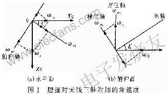
When the hull represents the disturbance with the angular velocity vector ωz = (ωpωyωh). Among them: ωy is the ship's roll speed, ωp is the ship's pitch speed, and ωh is the ship's heading speed. The changes of the ship's roll parameters are converted to the velocity components of the roll axis, azimuth axis, and pitch axis, as shown in Figure 1. Let ωRE be the additional azimuth speed of the ship roll, ωRC be the additional roll speed of the ship roll, ωRE be the additional pitch speed of the ship roll Deck coordinate system: OXc is the bow line of the ship, the bow is positive, and OYc is the vertical deck plane, upward If it is positive, OZc is determined by the right-hand rule.
Can be obtained from Figure l (a):

When A = 0 °, the pitch speed is ωp = 0, and only the roll amount ωy; when A = 90 °, the roll speed is ωy = 0, and only the pitch amount ωp. Under the combined action of active antenna drive and carrier disturbance, the total rotation speed of each axis of the antenna is:
Equations (2) to (4) are the reflection of the three-dimensional disturbance of the hull on the three axes of the antenna. The servo control system can use open-loop compensation to eliminate its impact on the antenna tracking. Equations (5) to (7) are the total rotation information of the three axes of the antenna in the inertial space. The servo control system can use a closed loop method to eliminate its influence on the antenna tracking. Therefore, it is the core of the anti-disturbance design of the servo system to try to measure the information correctly and adopt the appropriate control mode to suppress the disturbance so that the antenna can track the target quickly and stably.
2 Anti-disturbance design
Ship sway disturbance is introduced into the servo system as an interference signal. The principle of stable control is to detect such interference and reduce or eliminate its influence by adopting closed-loop or open-loop mode. Disturbance isolation methods include: rate gyro feedforward compensation, rate gyro feedback control, compound control and other methods. Because the gyro closed-loop control is essentially an error adjustment method. The gyroscope measures the comprehensive disturbance information, and cannot distinguish the disturbance information component from the follow-up information component. Therefore, while suppressing the disturbance information, the gyro loop also dynamically suppresses the active movement of the antenna, which reduces the response speed of the system and deteriorates the stability of the system. Relatively speaking, feed-forward compensation is an open-loop adjustment method. The measured disturbance information is added to the input of the speed loop to make the antenna shaft rotate at the opposite speed to the ship's roll to compensate. At the same time, since the structure and parameters of the tracking loop are not changed, the bandwidth of the system is not affected and the stability of the loop is good.
2.1 Compensation principle
The feedforward compensation method is to rotate the antenna in the opposite direction to the disturbance to overcome the influence of the disturbance. According to the reflection of the three-dimensional disturbance on the three axes of the antenna, the installation position of the gyro is reasonably designed to induce the movement speed of the three axes of the antenna relative to the inertial space caused by the ship's roll. The input end of the ring makes the rotation of the antenna axis opposite to the direction of the ship's yaw and the same amount of speed play a restraining role.
2.2 Control realization
The three-axis stability control of the antenna tracking device uses a tachometer as the speed feedback, and the encoder as the position feedback, and feeds the ship's disturbance to the speed loop through the rate gyro detection. The working principle block diagram is shown in Figure 2.

In Figure 2, K1W1 is the position loop correction control transfer function; K2W2 is the speed loop closed-loop transfer function, F (S) is the compensation channel transfer function, and the system transfer function is:
From formula (8), we can see that the loop following ability is determined by the term
According to the principle of complete invariance, when (1 + F (S) K2W2) ωf, that is, F (s) =-1 / K2W2, complete isolation of the ship's rocking disturbance is achieved, that is, when this condition is met, regardless of the amount of disturbance ωf is How big it has no effect on the output. However, the speed loop K2W2 contains integral, inertial, and second-order links. If you want to achieve complete invariance, there must be many differential links in F (S), so that the output of F (S) will be full of noise, making The system simply does not work. But it is possible to achieve local invariance. That is, the low-order differential is used to replace the high-order differential, and its coefficient satisfies certain conditions, so as to meet the requirements of system accuracy.
In actual use, the feedforward compensation coefficient is reasonably selected to maximize the feedforward loop to eliminate the current disturbance. On this basis, combined with the loop's following ability, the deviation of the visual axis is effectively eliminated, and high-precision tracking is achieved. Therefore, the feedforward loop plays the role of coarse adjustment, while the position tracking loop can be called fine adjustment.
2.3 Engineering application
2.3.1 Installation and measurement
Three speed gyros are used to measure the additional speeds in the direction of the azimuth axis, pitch axis and pitch axis caused by the hull sway, which are used for open loop compensation.
The pitch gyro is installed on the azimuth turntable, the sensitive axis is parallel to the pitch axis of the antenna, the gyro moves with the azimuth axis, and it is not sensitive to the rotation of the azimuth axis, the rotation of the pitch axis, the heading rate of the hull, etc., it is sensitive to the roll 3. The pitch rate, as shown in equation (2), can directly perform open-loop feedforward compensation on the pitch axis.
Analysis of the perturbation of the roll axis (Formula (3)) and the disturbance of the azimuth axis (Formula (4)) cannot be directly measured by a gyro, and can be obtained by an indirect method. Using two gyroscopes to measure cosAωy + s-inAωp and ωh, according to the pitch angle E, mathematically obtain equation (3) and equation (4). In this way, the rate gyroscope measuring the ωh component is installed on the azimuth base (without rotating with the azimuth axis), its sensitive axis is parallel to the azimuth axis, and the output is mainly the hull's heading rate information. The rate gyroscope measuring the cosAωy + sinAωp component is mounted on the azimuth turntable (rotates with the azimuth axis), and its sensitive axis is parallel to the roll axis.
2.3.2 Test and analysis
A shipborne three-axis antenna control system adopts anti-disturbance design. The sway experiment was carried out at sea, under typical sea state parameters (swing amplitude ± 6 °, sway period 12s). The antenna points to the satellite for self-tracking, and turns the ship's heading, so that the ship's pitch isolation of the pitch axis is measured when the ship is raised. At this time, the azimuth of the antenna is turned to 90 ° or 270 °; the ship's roll isolation of the roll axis is measured, and the azimuth of the antenna is turned to 0 ° or 180 °. The isolation test results are shown in Figure 3. In the figure, curve series 1 represents feedforward tracking data; curve series 2 represents no feedforward tracking data. The test results are: the ship roll isolation is 46.4 dB; the tracking accuracy is 0.031 °. From the above data analysis, it can be concluded that the open-loop compensation scheme fully meets the performance index requirements of the system design.

3 Conclusion
Feedforward compensation does not change the pole and closed-loop zero of the original closed-loop system. Therefore, it will not affect the servo bandwidth and stability of the system. The application of feedforward compensation and feedback control is used in the project. While ensuring the function and performance, it simplifies the system and improves the reliability and service life of the equipment. The actual use effect is remarkable.
Sheet Metal Bracket,Steel Forming Bracket,Stainless Steel Bracket,Sheet Metal Forming
Dongguan Formal Precision Metal Parts Co,. Ltd , https://www.formalmetal.com