1 Introduction
This article refers to the address: http://
The capacitive sensing type touch button has many advantages. Since the mechanical structure is not required, the touch button has an incomparable advantage compared with the conventional mechanical button and the film button, and thus brings a fashionable and beautiful design. It has been widely used in various consumer electronic products. More and more home appliances are beginning to use touch buttons, and induction cookers are one of the typical applications.
Cypress's touch technology Capsense is based on an application on PSoC products. PSoC (Programmable System-on-Chip) includes a programmable system-on-chip with an 8-bit microprocessor core and a mix of digital and analog signals. It not only has the MCU's programmable capability, but also includes some programmable logic functions. It also provides a programmable analog array with three programmable capabilities. In most home appliance touch applications, touch sensing processing and system control processing are generally included. PSoC provides the resources needed in this type of application and simplifies the system.
2. Induction cooker control principle and structure
The induction cooker uses the principle of magnetic field induced current heating. It uses alternating current to generate an alternating magnetic field through the coil. The alternating magnetic field generates an induced current (also called eddy current) at the bottom of the iron pot. The eddy current causes the high-speed random moving molecules of the iron of the pot to collide with each other to generate heat. Figure 1 is a block diagram of a typical induction cooker system.
The main circuit of the induction cooker is an LC resonant circuit with a resonant frequency of about 20-30 kHz. The resonant circuit is powered by a 310V DC voltage generated by the mains after rectification and filtering. The IGBT in the main circuit operates in a zero-voltage switching mode (ZVS) with low switching loss, which causes the coil and the resonant capacitor to generate a resonant voltage, thereby achieving electromagnetic conversion. In order to realize the control of the IGBT zero voltage switch, the voltage on the IGBT needs to be detected in the circuit, or synchronous detection, and the IGBT is allowed to conduct only when the voltage on the IGBT is close to zero voltage. The power adjustment of the induction cooker is realized by adjusting the PWM duty cycle of the IGBT power tube. When the PWM duty ratio is increased, the IGBT conduction time increases, the current supplied to the coil increases, and the power of the induction cooker increases accordingly. . The oscillator circuit is used to generate a PWM signal to drive the IGBT. The PWM duty cycle is determined by the resonant circuit and the reference voltage provided by the main controller. Typically, the main controller generates a reference voltage by outputting a PWM duty cycle signal and passing an RC filter. The current negative feedback control is to control the IGBT current by detecting the mains input current. The circuit processes the current sampling signal to reduce the on-time of the IGBT and reduce the average current of the IGBT. Other circuits include grid voltage detection, IGBT and pot surface temperature detection, surge protection circuits and other peripheral interface circuits. Through the above sampling and control circuit, the main controller can perform constant power control, constant temperature control, over-undervoltage protection, over-temperature protection and other series of controls.
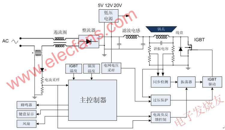
Figure 1. Block diagram of the induction cooker system
Since the induction cooker control panel and main circuit are usually placed in different positions in the induction cooker, most designs use two PCB boards for the convenience of design and maintenance – the power board and the user interface panel. According to the position where the master MCU is placed, it can be divided into the following three structures.
1) The master MCU is placed on the power board, and the user interface panel is a simple button and LED display. There is only one MCU in the system, the cost is low, and the two PCB boards are connected by more harnesses.
2) The master MCU is placed on the power board, and the user interface panel is controlled by another MCU. The two PCB boards are connected by fewer harnesses. Usually used in higher-end designs, panels can perform more complex operations.
3) The master MCU is placed on the user interface panel. The power board consists of several op amps and some discrete devices. The wiring harness between the PCBs is moderate, the system cost is low, and the panel can also perform more complicated operations. Most designs use this approach.
3. Touch button induction cooker controller
Since consumers pay more attention to the appearance of the stove when selecting the induction cooker, touch-type products are increasingly introduced into the design of the induction cooker. In the initial design, most of the discrete devices were used to design touch buttons. Although the cost is low, discrete device debugging is very difficult and not suitable for mass production, so most new designs use dedicated touch button controllers. The introduction of a touch-button dedicated chip increases the cost of the system and the complexity of the design, and changes the original system structure. PSoC integrates touch control and main control functions, which can upgrade the original non-touch induction cooker design to the touch cooker.
3.1 Introduction to CY8C22545
The CY8C22x45 family of products is Cypress's PSoC device specifically designed for touch applications and system control. Figure 2 is a system block diagram of the CY8C22x45, which has the same architecture as a normal PSoC product, including eight digital blocks and six simplified analog modules. These modules can be configured to be different peripherals based on customer specific needs, such as PWM generators, timers, ADCs, comparators, etc. The CY8C22x45 provides users with up to 38 general purpose I/O, 16Kbyte flash and 1Kbyte SRAM and other on-chip resources such as 10bit SAR ADC, voltage reference source (VDAC), I2C communication module, hardware real-time clock (RTC). This family of devices provides dedicated on-chip resources for touch designs and optimizes internal scan circuitry. Simultaneous scanning of dual-channel signals can be achieved without tying up other digital resources on the chip, thereby reducing the total scan time of all buttons.
The CY8C22x45 supports Cypress's CSA and CSD Capsense algorithms and supports a variety of touch designs such as buttons, linear sliders, round sliders, ITO touch screens and more. With the graphical design software provided by Cypress, users can easily touch detection and system control functions.
Perfect integration on the same PSoC controller.
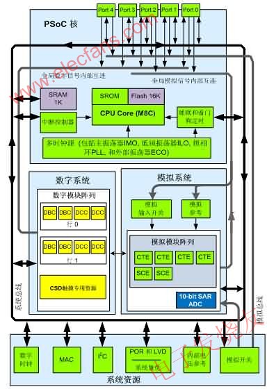
Figure 2. CY8C22x45 System Block Diagram
3.2 touch button design
The CY8C22545 contains optimized touch control logic on-chip, and Figure 3 shows the internal hardware block diagram of the device for CSD touch-sensing control of one channel. Compared with previous Cypress touch products, CY8C22545 products have the following characteristics:
1) CY8C22545 adopts the structure of two left and right analog buses. All IO ports can be connected to the analog bus on the left and the right through analog switches. All IO ports can be used as inputs to the touch sensor. In addition, the CY8C22545 is designed with two sets of scan control logic to support simultaneous scanning of two touch sensors, which reduces the total key scan time. This approach has unique advantages in the design of multi-buttons (or sliders) such as microwave ovens.
2) There are two current sources (IDAC) inside the device. Each current source has 256-level adjustment range, which can output 0"640uA current, which can replace the external discharge resistor used in various Capsense precision configurations. Therefore, only need An external charge and discharge capacitor can complete the detection of the sensing capacitor. In addition, the internal IDAC replaces the external discharge resistor. This method is very convenient for Capsense parameter adjustment, and the parameter can be optimally configured without replacing the external resistor. Of course, the customer You can still choose to use an external resistor as the discharge resistor for Capsense.
3) The scan clock source, counter and timer are all supported by dedicated resources, and do not occupy any digital module resources, so more digital resources can be used for system control.
4) In addition, due to the optimization on the circuit, an interrupt is generated after each key scan is completed, thus greatly reducing the CPU intervention time, so that the CPU has more time to handle other tasks.
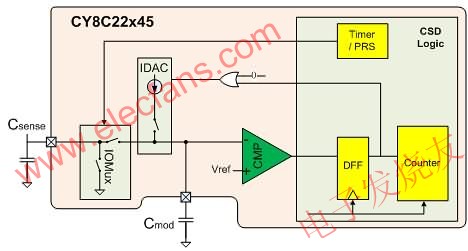
Figure 3. CSD touch-sensitive control logic block diagram
3.3 System Design
This design adopts the more popular induction cooker structure on the market, that is, the power board is composed of one piece of LM339 and some discrete devices, and the user interface board is composed of discrete components such as MCU and LED. The power board implements control including synchronous detection, current negative feedback control, oscillation circuit, surge protection, etc., which will not be described in detail in this paper. User interface board realizes touch sensing control, LED digital tube and LED light scanning drive, user menu management, IGBT and pot temperature detection, over temperature protection, power supply over voltage and under voltage protection, induction cooker constant power control, constant temperature control, fan, Peripheral controls such as buzzers and other system master functions. Figure 4 is a hardware block diagram of the user interface board.
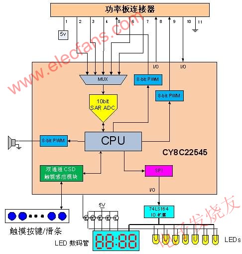
Figure 4. User Interface Control Board Block Diagram
The CY8C22545 is available in a 44-pin TQFP package with up to 38 I/Os and supports up to 37 touch sensor inputs, making it ideal for most complex user interface boards. If the number of IOs cannot meet the demand, the user can complete the expansion of the IO port with an external 74LS164 through the SPI interface for driving peripheral devices such as LEDs.
In this design, the CY8C22545 detects the external 12 touch-sensitive buttons. The SAR10 ADC samples the voltage and current of each temperature sensor and AC power supply, and uses three digital modules to configure three 8-bit precision PWM generators. It is used to drive the buzzer, control the fan speed and generate the PWM reference signal for power control. In addition, a digital module is configured as an 8-bit timer for the time base of the firmware. If an IO extension is required, a digital module can be configured as an SPI interface to drive external serial to parallel conversion logic.
Constant power control and constant temperature control are the two main modes of operation of the induction cooker. In this system, two PID closed-loop control algorithms are adopted to realize constant power control and constant temperature control. Since the two systems have different time parameters, it is necessary to separately adjust the setting system PID parameters.
No-pot detection is an important technique in induction cookers, which includes placement detection and removal detection. The placement test is pulsed. Before the induction cooker is working normally, the CY8C22545 turns the main resonant circuit on for a small time and detects the number of oscillations of the resonant circuit by counting the number of resonant zero crossings. When there is no pot, the main resonant circuit is in an underdamped state, and more pulses are generated at the detecting end of the resonant zero crossing. When there is a pot, the main resonant circuit is in a damped state, and the pulse generated by the resonant zero-crossing detection end is less. The CY8C22545 is able to determine if a pot is present by detecting the number of pulses. The method of current detection is used for the removal detection. When the induction cooker is working normally, the working current will stabilize within a normal range. If the pot is removed, the system current will drop dramatically to a smaller extent. CY8C22545 can be used to determine the removal of the pot by detecting a sharp drop in current. In addition, the system's operating current is maintained at a specific range under the condition that the CY8C22545 outputs a fixed duty cycle PWM. The CY8C22545 can also determine if the pot is removed by detecting if the current current matches the duty cycle of the current PWM.
4. Conclusion
The PSoC CY8C22545 touch-button induction cooker design utilizes its analog, digital, and touch-sensing logic to enable the entire system to use only one PSoC chip to implement the touch-button induction cooker control. The structure is very simple and clear, and does not require too many peripheral components. It is very flexible and convenient in parameter adjustment of touch sensing, saving a lot of debugging time for customer's design and production.
Headphone speaker is a king of speaker unit which is used for headphone, it also called headphone driver. These speakers have high sound pressure level, fast frequency response, wide frequency response range and low distortion. Headphone Speakers are mainly used for voice headphone (e.g. customer service phone, call center headphone, military intercom headset- ) and music headphone (e.g. Bluetooth headphone, sport headphone, game headphone-).
Our main headphone speakers include:
1) From the diameter, we have speakers in 23mm ~ 57mm.
2) From the impedance, we have speakers of 32ohm/150ohm/300ohm/1000ohm.


FAQ
Q1. What is the MOQ?
XDEC: 2000pcs for one model.
Q2. What is the delivery lead time?
XDEC: 15 days for normal orders, 10 days for urgent orders.
Q3. What are the payment methods?
XDEC: T/T, PayPal, Western Union, Money Gram.
Q4. Can you offer samples for testing?
XDEC: Yes, we offer free samples.
Q5. How soon can you send samples?
XDEC: We can send samples in 3-5 days.
Intercom Headphone Speaker,Call Center Headphone Speaker,Military Headphone Speaker,Voice Headphone Speakers
Shenzhen Xuanda Electronics Co., Ltd , http://www.xdecspeaker.com