The cyclone preheater is a heat exchanger composed of a cyclone tube and connecting pipes. It uses the high-temperature exhaust gas of the cement rotary kiln to heat the cement raw material. We intercepted the first-level prototype of the five-level cyclone in the actual project and scaled it down, and made some improvements for the needs of comprehensive teaching practice and scientific research to construct a complete and open teaching and research platform. The whole system is composed of cyclone preheating cylinder equipment, single chip microcomputer control system, speed regulating fan, electric heating and other execution devices and its host computer management system.
In this paper, the design and implementation of the hardware and software of each component are explained, and its technical characteristics are explained in detail. Finally, several teaching and research results based on this platform are given.
1 Composition of teaching and research platform system
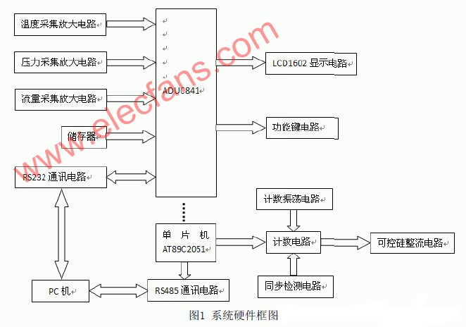
The entire teaching and research system is composed of cyclone preheating cylinder equipment, single chip microcomputer control system, speed control fan and electric heating and other executive devices and its host computer management system. The cyclone preheating equipment can be regarded as a conical body with a cone at the bottom and a cylindrical body at the top, which is consistent with the actual engineering cyclone preheating cylinder. The whole device is made of transparent organic plastic for easy observation and observation. The cylindrical tube wall has many small holes distributed in layers, which can be equipped with various sensors according to the experimental needs. The outlet of the speed regulating fan is connected with the conical bottom through the air pipe, and at the same time, an electric wire is provided at the air pipe. The electrical signals in these systems are connected to the single-chip system. The single-chip microcomputer control system is the core of the cyclone preheating teaching research platform, and its hardware block diagram is shown in Figure 1.
The general data flow is that all kinds of sensor signals are read into the ADUC841 and temporarily stored in the memory, and the information is displayed on the LCD at the same time. Then upload the data to the upper PC through the serial port upstream. At the same time, the host computer sends the control information to AT89C051 through the serial port, which cooperates with synchronization, detection, and technical circuits to trigger the thyristor to control the motor speed.
The teacher hopes that we will practice more in the production process of the platform, so the starting point of the hardware and software technology used in the design of the platform is basically within the scope of the undergraduates' ability.
2 SCM control system
2.1 ADuC841 peripheral circuit design
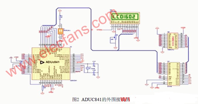
The whole system is composed of ADUC841 microcontroller [3] [4], LCD display circuit, DAC output circuit, ADC acquisition circuit, RS232 communication circuit, etc. It mainly detects the temperature, pressure, air flow and other signals in the cyclone in real time, and uploads the data to the PC. The following figure is the wiring diagram of ADUC841. It can be seen from the figure that the bus connection scheme is: using wire selection to connect to the high-density memory chip 62256, that is, when P0 is used as the address line, it is first connected to the octal tristate latch 74HC573 and then connected to the lower 8-bit address line of 62256RAM On the top, P2.0-P2.6 is directly connected to the upper 7-bit address line of 62256RAM, while P2.7 is connected to the chip select signal to achieve access to its 0000H-7FFFFH space. The connection with LCD and MAX485 adopts the full decoding method. When the 4, 5, and 6 pins of P2 port are used as address lines, they are connected to the ABC of 74LS138. After decoding, they are used to control the LCD display and serial communication. When the P0 port is used as a data line, it is directly connected to the data line of the RAM and the LCD.
2.2 Signal acquisition and amplification circuit
Driven by a constant current source, first the instrument amplifier AD620 is used to amplify the signal from the sensor. The LM324 with four integrated op amps forms a conventional forward voltage amplification and follower circuit, which is used to detect the signal amplification and shaping. Because the 12-bit ADC integrated in the ADUC841 is connected to the P1 port by default, the amplified and shaped detection signal is directly connected to the P1 port to realize the reading of the analog detection signal. In the single-chip microcomputer, the collected detection signal is converted into digital quantity and some dimension changes are made, and then it is output from its TXD / RXD port.
The signal is first replaced by MAX232 to TTL level to RS232 level, and then connected to the serial port between the host computer through the system serial port. Realize uploading the collected signals of each sensor to the PC, the digital power supply and the analog power supply adopt 7805 voltage stabilization respectively, and there is a light-emitting diode at the output capacitor as the power supply indication.
2. 3 thyristor control circuit
The thyristor control board is composed of three parts: 1. Count oscillation generation circuit; 2. Synchronous detection circuit; 3. SCR control circuit. The counting oscillation generating circuit uses 16.384MHz active crystal oscillator as the counting pulse oscillation source, and uses 74LS14 Schmitt trigger to shape it [7], after the counter 74LS90 decibel frequency and CD4020 sixty-four frequency division, the frequency is 25.6 The oscillation pulse of kHz counts the CP end of CD4516 [7].
The synchronous detection circuit uses a 220V / 15V transformer to obtain 15V AC, and then performs full-wave rectification on it, and then uses a synchronization circuit composed of a photocoupler TIL113 to obtain a pulse sequence synchronized with the true zero-crossing point of the sinusoidal signal. The synchronous signal of the thyristor is sent to the preset terminal PE of the preset counter CD4516.
An 8-bit binary addition counter composed of two CD4516 cascades is used in the system to count the oscillation pulses with a frequency of 25.6 kHz. Since the count pulse frequency is 25.6 kHz, theoretically there should be 25600 / (2 * 500) = 256 count pulses at 180 degrees; the phase resolution is 180/256 = 0.7 degrees. In this way, the value that makes the thyristor fully on corresponds to FFH (decimal number 255); the value that makes the thyristor turn off corresponds to 0. Obviously, if you want the thyristor to start conducting from the angle θ, the counter needs to count θ * 256/180 to take the entire pulse.
AT89C2052 receives the control signal from the serial port of the host computer (0-255 corresponds to the expected conduction angle), converts it into an eight-bit binary number, and then distributes it to the two preset numbers of CD4516 through its P1 port. When the sine wave crosses the zero point, the synchronized pulse is 1 input to the preset terminal PE of the CD4516, and the preset value is written into the CD4516. After the zero crossing of the sine wave, the synchronized pulse is 0, and the CD4516 starts pulse counting. When the count reaches the preset value, its CO terminal outputs a negative pulse, which is sent to pin 2 of the optocoupler MOC3020 after the driver 7407 to trigger the thyristor G pole and turn on the thyristor to drive the motor. In this way, the input voltage of the fan is controlled by controlling the conduction angle of the bidirectional thyristor, so as to obtain different motor revolutions and then obtain the preset air volume.
3 upper computer management system
The upper computer management system is composed of a conventional C / S system by the front interface and the background database. At the same time, it contains the communication processing program for data interaction with the single chip system through the serial port.
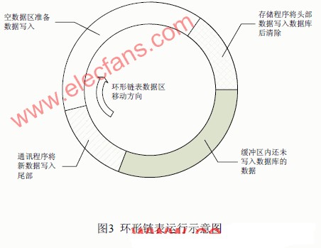
Technically, VB's MsComm control [10] is mainly used to send the control commands of the host computer to AT89c2051, and at the same time read the detection data signal sent from ADU841. The difficulty here is the coordination between the serial communication program and the database storage program. After many tests, the circular link list buffer solution is adopted. That is, in response to the ComEvReceive event [8], the serial communication program writes the data transmitted by the single-chip microcomputer into the end of the data area of ​​the ring list (nodes are simultaneously marked with time stamps). At the same time, the timer periodically triggers a storage event. Through ADO, a certain amount of node data in the head of the circular link list data area is written to the table in the SQLServer2000 database. After successful storage, the node content is emptied for the serial program to write new upload data. space. See Figure 4 Schematic diagram of the circular linked list. By reasonably setting the number of nodes in the ring list, the baud rate, and the interval between timer events, the average throughput rates of the two operations of writing and reading and clearing in the buffer can be kept the same. This can achieve efficient operation of the program, while the fixed buffer storage area scheme is more stable than the dynamic array open space scheme.
On the front-end interface, the user can directly choose to set the port data, display the signal data of interest and control the fan and other devices. In order to facilitate data retrieval and display, different views of the test signals and conventional processing stored procedures are built in the database. In order to achieve the display, playback and analysis of relevant data.
Empty data area ready for data writing
4 Related teaching and research results
Based on this teaching and research platform, many batches of open trials have been launched. The design and ongoing are: sensor numerical display and protection circuit, serial port to USB port communication software and hardware design and implementation, database data conventional statistical storage process and so on. At the same time, some students joined the platform to carry out research to complete the master thesis, flow temperature tpye2 fuzzy control system, ARM-based cyclone preheater touch screen human-machine interface system [5] [6] design work, etc. The students generally reflected that by participating in the relevant open experiments and research on the platform, they deepened their understanding of the knowledge they learned and were easy to master the skills they learned.
5 Conclusion
The author's innovation in this article lies in: Based on on-site engineering objects, a simplified and innovative design of a cyclone preheater teaching and research platform is made. The entire system covers a complete set of functions and processes such as data acquisition, speed control, data storage analysis, etc. It is typical and open.
Practical results show that the exploratory comprehensive open experiment conducted on it can better train students' comprehensive and practical abilities than the verification experiment of traditional teaching. At the same time, due to the ambiguity and complexity of the model, it is also a good platform for teachers and graduate students to carry out control strategy research based on spatially complex objects.
references
[1] Chi Hongjun, Chen Lijun. Design of control system for cyclone preheater of cement rotary kiln based on ARM and μC / OS-II January 2008
[2] Fu Jianling, Zhao Lei. Design of the control system for the cyclone of the cement rotary kiln based on ADUC841 July 2008
[3] ADIC841Datasheet. AnalogyDevices, lnc. 2003E.
[4] ADiC841User'sManua1. AnalogyDevices, lnc. 2003 [J]
[5] Zhang Aiping. LabVIEW entry and virtual instrument [M]. Beijing Electronics Industry Press. 2005.
[6] Zhang Xi, Wang Xiaofeng. Design and implementation of virtual oscilloscope based on labview [J]. Electronic Test. 2007 (6): 21-25.
[7] Kang Huaguang. Fundamentals of electronic technology [M]. Beijing Higher Education Press, 1999
[8] Dianezak. ProgrammingWithMicrosoftVisualBasic6.0 [M]. Electronic Industry Press, 2002
[9] Microchip. MAX0382007 Microchip Technology Inc: 32-41E.
[10] Jiang Jingbo, Li Siren, et al. Design of a multi-channel real-time acquisition system for marine elements [J], Microcomputer Information, 2009, 25-4: 91-92
Hengstar provides a range of Industrial Fanless Pc for industrial automation environments. The PC is powered by a fanless Industrial Motherboard, with onboard Intel Atom N270 1.6G Hz CPU or Intel Atom D525 dual core 1.8G Hz CPU, and a Solid State Drive, making the PC very compact and rugged in structure. We also have H61 motherboard. It supports Intel Core i3/i5 CPU. Customer can have a high-performance PC by using this H61 motherboard. Hengstar`s industrial fanless PCs suit for the harshest industrial environments and comply with various international NEMA and IP standards.
Fanless Industrial Computer,Industrial Fanless Pc,Fanless Embedded Computer,Fanless Touch Panel Pc
Shenzhen Hengstar Technology Co., Ltd. , https://www.angeltondal.com