Environmental design directive development background
On July 6, 2005, the EU President signed the EU Directive 2005/32/EU (Environmental Design Directive), which sets the framework for the environmental design requirements for Energy using Products (EuP).
This article refers to the address: http://
The EU requires member states to translate and implement the environmental design directives into national laws, regulations and management regulations. For example, Germany facilitated the issuance of the EbPG (Energiebetriebenen Produkte Gesetz, Energy Use Products Act) Act on March 7, 2008.
The first important question is: What is the purpose of this directive?
The main objectives detailed in the Directive are as follows:
1. Achieve coherence between the laws and regulations of member states to ensure the free flow of energy-using products in the EU market.
2. Continuously reduce the impact of EuP on the environment.
3. Optimize the environmental performance of the product while maintaining its functional quality.
4. Improve energy efficiency and reduce greenhouse gas emissions.
5. Most of the environmental pollution problems caused by the product during the life cycle can be solved in the design stage, so various environmental design actions should be taken during the design phase.
6. Establish a framework for environmental design requirements.
7. Minimize the potential environmental impact of the product.
In addition, Article 3 of the Directive (marketing and/or service provision) requires all Member States to take all effective measures to ensure that only the EuP that has passed the relevant assessment and is affixed with the CE mark can be launched. Failure to comply with the regulations will result in penalties, and related products must be withdrawn from the market.
On November 22, 2007, the first study prepared for the first work plan was completed - "Research on the first work plan for preparing environmental design directives." The 426-page study fulfills the content of Article 16 of the Directive, which is intended to list the list of energy use products that were first included in the implementation. The instructions will process these products first.
The study identified 600 products into the scope of the Environmental Design Directive and defined 57 product categories, 34 of which were implemented first.
The first 34 products implemented in this category are further divided into priority A products (25 products) and priority B products (9 products).
Advance research, working documents or draft regulations for the products listed in Table 1 are in place. Two of the final regulations have been formed.

An preliminary study of the product categories listed in Table 2 has been completed.
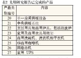
The preliminary research report on transformers, refrigeration equipment, audio and video editing equipment has also been completed, but the category number has not been specified.
After the draft regulations are published in the Official Journal of the European Union, they will become final regulations and will enter into force in all EU member states after the 20th.
Specifications for the set-top box specifications and standby power consumption have also been in effect. The set-top box specification differs in that it also specifies the standby power consumption and normal operating power consumption of the set-top box.
Standby power specifications are a challenge for product manufacturers and semiconductor companies. Manufacturers will have to adjust their products quickly in a short period of time in accordance with regulatory requirements, and semiconductor companies must provide innovative devices to developers to meet the following requirements:
One year after the specification is implemented, the power consumption in any shutdown mode must not exceed 1W; after 4 years, the power consumption should not exceed 0.5W in any shutdown mode, and if the product has a reactivated operating mode or provides information The status shows that the power consumption must not exceed 1W. In addition, the product must have a special feature that automatically switches the device to standby, shutdown mode, or any state that meets power requirements in the shortest possible time.
Semiconductor devices that reduce standby power and shutdown mode power consumption To meet these demanding requirements, Fairchild offers a broad portfolio of products, the FSQ product line of Fairchild Semiconductor Power Switch (FPS). This family of devices achieves high efficiency during normal product operation and very low power consumption in standby mode.
These power switches use valley-switching technology to minimize primary conduction losses for high efficiency. During turn-on, the conduction loss is proportional to the voltage on the power switch. At this time, by minimizing the voltage conduction on the switch, the loss can be minimized and the efficiency can be improved.
In addition to valley conduction technology, the device uses a technique called Burst-mode to minimize power consumption under light load conditions.
Even if the product uses a display that consumes 0.5W, it is still easy to achieve a total standby power consumption of less than 1W.
Figure 1 shows the schematic of a FSQxxx power supply with a flyback topology.
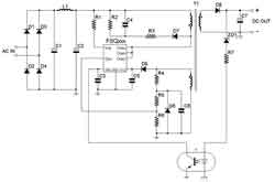
Figure 1 Schematic diagram of a flyback power supply based on regulator FSQxxx
To achieve valley bottom conduction (quasi-resonance), the following devices must be available: R4, R5, R6, D6, and C6 (see Figure 1). By connecting these circuits to the auxiliary secondary winding of the transformer and the sync pin (Sync-Pin) of the regulator, the valley bottom can be detected. With a fixed program, the regulator can switch the integrated power switch at the bottom of the drain voltage. Figure 2 shows an example of the measured voltage and current waveforms.

Figure 2 Valley bottom conduction (red: drain source voltage; green: drain source current)
This intermittent mode of operation only occasionally switches the regulator at light loads. In this mode, the output voltage ripple is slightly higher, but it is negligible for standby mode. Usually only the display is connected to display the standby mode. The simplest example is an LED or a remote receiver.

Figure 3 Intermittent mode (top to bottom): output voltage VO, feedback pin voltage VFB, drain source current IDS, drain source voltage VDS
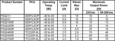
Table 3 lists the power regulators with integrated valley turn-on and intermittent modes of operation, which are suitable for an output power range of 8 to 90 W (the exact number depends on the input voltage range).
Table 3 FSQxxx Series with Integrated Valley Bottom and Intermittent Mode
The FSQ510 and FSQ510H are regulators with special functions (as shown in Table 4). They only have intermittent operation mode and no bottom conduction function. With these devices, standby power can be as low as 60mW. These regulators are designed for maximum output power of 9W. Since the conduction loss of this power range is very low, the use of valley conduction does not bring any advantages.
Table 4 FSQ510 Series with Integrated Intermittent Mode and Low Standby Power

Drive devices for motor and water pump, commercial ventilation applications
The products of circulating pumps and ventilation systems will be discussed first, and the same principles can be applied to other applications with similar requirements.
Compact designs with fewer components are becoming more and more important for a variety of reasons, such as energy efficiency. In addition, life cycle and reliability requirements play an important role.
Figure 4 shows a schematic diagram of the pump used in the heating system. The purpose is to transfer the heat stored in the hot water to each connected radiator quickly and efficiently.
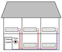
Figure 4 Schematic diagram of the heating system of a two-story residential building
The water pressure required for the heating system depends on the distance between the heat generating system and the radiator and the height difference that must be overcome. Therefore, the water pressure must be adjusted separately. In many cases, each layer will be connected to a separate pump.
In the past, water pressure was adjusted by simple TRIAC control (usually in three steps).
TRIAC control can only be used for general-purpose electric motors. Its disadvantages are: high total harmonic distortion (THD), high input power consumption, and low regulation efficiency.
The use of smart inverter-based drives connected to modern BLDC (brushless DC) motors can increase efficiency (up to 70% energy savings), enable efficient and intelligent control of heating systems, and reduce natural energy consumption and emission of greenhouse gases.
Solar and heat pump applications have emerged as heating and hot water systems have increased demand for alternative energy sources. The requirements for these applications are very similar to those used in heating applications. To transfer heat through the medium (water or hydraulic oil), it is always important to control the “pressure†value efficiently. A similar situation applies to air conditioning, even when we talk about higher power levels. The development and use of inverter-based solutions is driven by various energy efficiency regulations and government restrictions.
Fairchild's Smart Power Module (SPM) product line is designed for power ranges up to 120W and is available in TinySMD and TinyDIP packages to replace nine discrete devices with a small footprint. Figure 5 shows a schematic diagram of a typical inverter application using a TinyDIP module. To develop a space-optimized printed circuit board, only a few external components (including a microcontroller) are required in addition to the module.
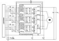
Figure 5 Typical inverter application
The Environmental Design Directive takes into account factors such as the life cycle discussed earlier. Both TinyDIP and TinySMD modules are pre-tested and optimized subsystems, reducing FIT rates (failure rates), enhancing overall system reliability, ultimately accelerating the design process, speeding time to market, and helping to achieve discrete ratios. The solution has a smaller footprint.
In addition to family homes, public buildings such as office buildings, factories, and schools and hospitals also require heating and ventilation systems.
For current modern building management, separate, levelless adjustment and control are common requirements. Equipment used in this type of environment has a power range of between 100 W and kW.
Large equipment will undoubtedly have more adverse effects, such as increased energy consumption and total harmonic distortion. This in turn affects the operational performance of other devices, such as IT infrastructure.
Fairchild offers a portfolio of power modules for higher power ratings. Since higher power levels typically require heat sinks, these modules provide good heat sink connection performance and are more suitable for high power level applications than small TinyDIP and TinySMD modules.
The MiniDIP module is available in three different versions, the fully molded MiniDIP module, the ceramic MiniDIP module and the DBC MiniDIP module. The three versions are pin-compatible with each other, the main difference being the thermal connection to the heat sink and the corresponding mounting area.
There are two versions of the DIP module, the ceramic DIP module and the DBC DIP module.
The DBC versions of the MiniDIP module and the DIP module are shown in Figures 6 and 7. Figure 8 compares the cross-sectional differences between the ceramic DIP module and the DBC DIP module.
In Fig. 8, the semiconductor elements are marked in blue, the bond connections are marked in black, and the lead frame is light gray.
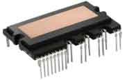
Figure 6 MiniDIP Module (DBC)
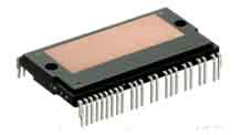
Figure 7 DIP module (DBC)
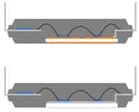
Figure 8 Cross section of the DIP module, the above figure is the DBC version, the figure below is the ceramic version
Regardless of which type of module the module is, its internal drive components are soldered directly to the leadframe (left side of the figure).
In the ceramic type, the power device is also soldered directly to the leadframe while the leadframe is bonded to the ceramic. Ceramics can achieve an isolation voltage of 2.5kV and good thermal connectivity to the heat sink.
The DBC is a two-sided copper-clad ceramic substrate, and the copper area outside the module is homogeneous. The power device is soldered to the internal structure of the copper region, similar to a PCB. The two copper areas provide the equivalent of a thermal diffuser, so the thermal impedance is lower than the ceramic based solution. This technology also provides 2.5kV isolation.
Summarizing the implementation of environmental design directives and related regulations is an important method to achieve high energy effects. These directives and regulations give semiconductor suppliers significant opportunities to develop highly integrated, energy-efficient solutions to meet the requirements of these regulations.
Biomass Cook Stove,Wood Cook Stoves,Outside Camping Pellet Stove,Biomass Camping Stove
xunda science&technology group co.ltd , http://www.gasstove.be