Designing digital systems using VHDL language, most of the design work can be done on a computer, thus reducing system development time and improving work efficiency. The following describes a scheme for designing a traffic light controller based on VHDL, and gives the source program and simulation results.
1 system functions and requirements
The traffic light controller controls the traffic at the intersection of two main roads. There are many vehicles at the intersection. The straight-line signal and the left-turn signal are displayed separately. The transit time of the two main roads a and b is equal, and the green light indicating the straight line is bright for 30 s, indicating the left. The turn green light is on for 12 s. When the green light changes to red light, the yellow light is on for 3 s, so that the vehicle can stop in the parking line, and the corresponding yellow light of the last 3 s of the red light signal is also on, in order to prompt the driver to prepare for the start. . Sensors are provided at both main road junctions to detect the presence or absence of vehicle traffic. When the two main roads have vehicles, they are automatically in the green light of the main road, the red light of the main road b, and then the traffic is switched in turn. When the main road a has no vehicles, it is automatically in the main road b green light, the main road a red light state; and vice versa, to improve the traffic efficiency.
2 Design and simulation
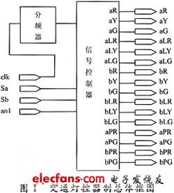
According to the function and requirements of the traffic light controller, the overall circuit is divided into two modules: frequency divider and signal controller. The frequency of the external pulse oscillator is selected as 32 768 kHz, the frequency divider is divided into 1 Hz signal, the 1 Hz signal is used as the counting pulse of the signal controller, and the frequency divider and signal of the traffic light controller are designed by VHDL. Two modules of the controller, on the QuartusII development platform, compile the VHDL programs of the two modules separately, and then form the overall block diagram shown in Figure 1 by using the schematic input method.
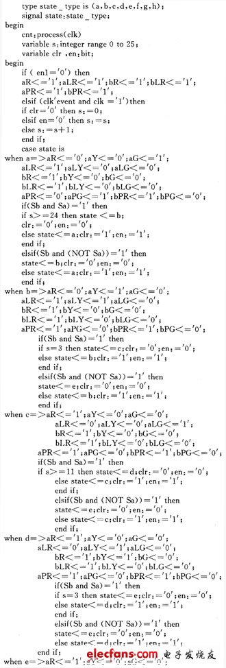
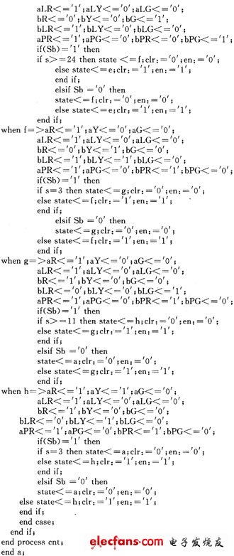
The VHDL program of the signal controller is as follows:
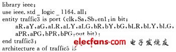
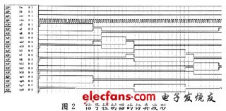
Among them, Sa, Sb are the signals of the a and b intersection sensors respectively, aR, aY, aG, aLR, aLY, aLG respectively represent the straight red, yellow and green lights controlling the main road a, the left turn red light, the yellow light, The signal of green light; bR, bY, bG, bLR, bLY, bLG respectively represent the red, yellow and green lights of the main road b, the red, yellow and green lights of the left turn; aPR, aPG, bPR, bPG Is the sidewalk signal, enl is the enable signal. When enl=0, the red lights of both a and b are bright at the same time, which is convenient for handling special situations. Using QuartusII to compile and simulate the program, the simulation waveform obtained is shown in Figure 2. After program download and experimental verification, the system function meets the requirements.
The traffic light controller is designed based on VHDL, with few peripheral circuits, low power consumption and high reliability, which is convenient for system function modification and high design efficiency.
Remote Trainer,Auto Trainer,Remote Collar,Best Remote Dog Training Collar
Elite-tek Electronics Ltd , https://www.aetertek.ca