Model-driven development environment strengthens software development process
In today's interconnected world, medical equipment naturally accommodates more innovative features with intelligent functions. These new capabilities are usually designed with software; therefore, the software used to implement these new functions is becoming increasingly complex. At the same time, FDA and other regulatory agencies are also gradually putting pressure on medical device manufacturers to ensure product safety and the accuracy of information about medical device reports.
Faced with increased product complexity, market pressure, product safety and regulation, it is good business sense for medical device companies to respond to these challenges. This article explores a model-driven approach to developing medical device software.
Equipment manufacturers are at a turning point in software development, and several tools may help them improve productivity and quality. A model-driven development process integrates the various stages of product development, from requirements analysis to system design, implementation, documentation, and testing. This workflow helps enable complex requirements and architecture to be graphically represented in charts, thus reducing complexity and also helping shareholders communicate requirements and designs. Charts are semantic and interconnected, helping to achieve traceability directly from design requirements to design. Furthermore, the software implementation can be directly generated by the model, providing follow-up inspection from design requirements to design to implementation.
Deliver equipment software
In the medical device market, the impetus for delivering innovative technologies is very realistic, and smart devices are everywhere. In this area, it is the software that provides the functions that make the high-tech world possible. Medical device software is used to perform functions that might have been implemented in hardware in the past: for example, physical knobs and buttons on diagnostic devices are often replaced by touch screen displays, or medical images such as X-rays and MRI are gradually delivered in digital format instead of physical film .
The medical market is fiercely competitive, and it is essential that products are marketed before competition. Completion of pre-marketing activities (such as the 510 (k) process) and subsequent pharmaceutical production and quality management (GMP) are essential for the introduction of equipment to the market and occupy a strong market share. However, a balance must be struck between speed and patient safety to avoid costly product recalls. One of the strategies is to reuse existing large amounts of equivalent programming code for pre-market activities, especially when working with software for life-critical operations. The key path to achieving successful software is through understanding; in some cases, the software may be aging and the programmer is no longer in the company, that is, why effective reuse depends on understandable documentation.
Documentation! Documentation! Documentation!
Organizations that can make use of their intellectual property (IP) effects—and can reuse—are already one step ahead in engineering new medical device software. For reuse, nothing is more important than drug documentation, and it has other effects. For maintaining project information, a design history file (DHF) is used to store project results. FDA manages products developed for the US market by requiring a DHF quality system monitoring (QSR), 21 Federal Management Code (CFR) Part 820.30. The DHF contains relevant information from a variety of sources, including items such as requirements, system specifications, risk management, and other formal documents. It may also include notes, sketches, or other fragmentary information. The basic principle behind having a DHF is to provide traceability and documentation to show that the device is used for a specific purpose, and its design fulfills all requirements. However, how to achieve this is somewhat accidental: some companies use source code to print lists to prove that they have fully implemented the design requirements. Of course, using source code as a communication method is only effective if the reader can understand the code. Non-technical shareholders may lack the skills required to read the source code, creating a potentially dangerous communication vacuum.
Visual software development
Model-driven development (MDD) creates a visual development environment for software delivery. The foundation of MDD is the Unified Modeling Language (UML) derived from the object management organization. The MDD environment visualizes complex design inputs and facilitates communication between various shareholders. The development team can express the design requirements, architecture, structure, design, and behavior in a format that is easier for shareholders to understand than the source code. UML defines several different diagrams to obtain the organization, architecture, and behavior of a system or application. Similar to UML, System Modeling Language (SysML) is based on UML, but is tailored to the needs of system engineering design.
The information in UML charts is stored in a model repository, which greatly expands the role of charts as illustrations only (see Figure 1). The change of information on one chart is reflected by the model repository and transmitted to other charts to reflect the same information. For example, suppose there is a level named "Pump" in the design, and the same level appears in two different charts. Changing the name "Pump" to "InfusionPump" in one picture will automatically change it in another picture.
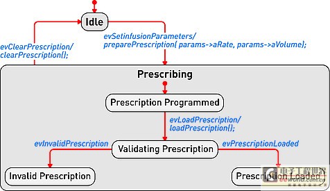
Figure 1: Device operation mode described in the form of a state diagram.
Track design requirements to model components
The requirements for medical equipment are usually specified in text files or exist in the requirements management tool used as design input. Although the text can communicate a lot of details that need to be completed, it can also be susceptible to misunderstandings. More importantly, there are no filters or procedures to prevent conflicting design requirements from being recorded at the beginning. By splitting the requirements into further detailed requirements for each component in the product, performing a requirements analysis can help resolve conflicts. Modeling can aid this process by visualizing the textual requirements in the form of charts and provide traceability to design and implementation.
The first step in tracking requirements to model elements is to relate text requirements to the modeling environment. A requirement component within the model stores requirements and maintains text describing requirements in addition to other relevant information such as requirement ID, priority, safety integrity level, and risks. There are no restrictions on the types of data that can be stored. Requirements and models are kept in sync so that changes from either side can be reflected on the other side. The traceability of the model elements from requirements to meeting these requirements is expressed in the model. With this information, you can generate demand coverage reports or analyze the impact of design changes. For example, a UML data can be generated, and a fault tree analysis chart is defined. Security and risk analysis can also be performed within the model. Figure 2 shows how the fault can be traced to the design requirements related to the fault. Further model information analysis can be performed to illustrate the coverage gap.
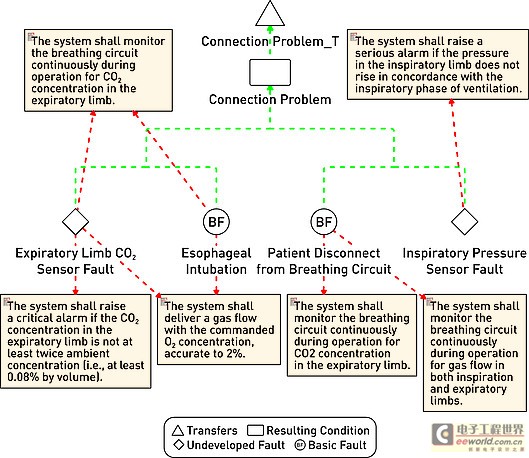
Figure 2: Model elements that track requirements to meet design requirements.
Work with code and models
Medical device manufacturers have verified and tested the software used in existing devices that can be used by future devices. The software can be introduced into the modeling environment. UML code diagrams can be automatically created to show the existing structure, architecture, and behavior of the code. The result is better documentation of existing codes, which will help new developers or other shareholders obtain codes that are easier to understand for specific purposes.
Once described in the model, traceability to the design requirements is added to the existing code and can be used to assist in creating new features that have been developed within the model. For example, a new type of user interface may be created for an infusion pump, but the existing code to deliver medication to the patient should be reused. The user interface code simply references the existing code, and the relationship between the two is established within the model.
As a design process, more details and behaviors are added to the model. UML provides equipment for all applications within the specified model, and detailed target-level code is also included in the model. Device-oriented code can be generated directly from the model. This helps to create traceability from code to design within the model. The design requirements are also included in the model, so traceability is achieved from the requirements to the implementation code (see Figure 3). It is possible to include requirements information directly in the code as an assessment of the further traceability between requirements, design, and implementation.
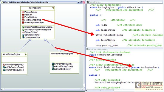
Figure 3: Code generated from the model can be traced from design to implementation.
Software developers do not need to abandon their current development environment to adopt a model-driven approach. The code generated from the model can be compiled into their code editor of choice, and the model can be automatically updated and changed (see Figure 4). This keeps the implementation synchronized with the design.
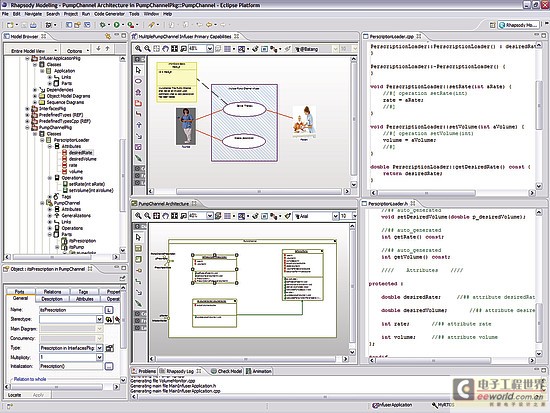
Figure 4: Model-driven development integrated into an existing development environment such as Eclipse.
Checksum verification
FDA guidelines recommend starting verification at the initial design input and continuing verification iterations throughout the development process. Most defects enter the system during the initial analysis stage of development, but are usually not discovered until the integration stage. The model-driven approach uses model execution and consistency verification to identify problems early in the most easily determined product design. Using this model, it is possible to generate production quality codes, including C codes.
For medical device engineers, model execution running on the host platform can verify design behavior just before the hardware may be ready for software testing. When hardware is available, engineers can focus on target-specific problems, such as timing.
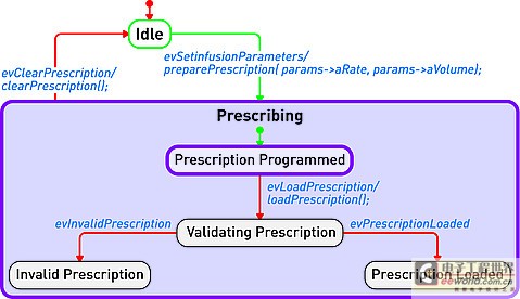
Figure 5: By highlighting design behavior, model execution helps achieve early verification.
Document production
Using the model-driven approach, because software developers create models, they also provide documentation for their designs. The diagrams in the model visualize the design and can be used to communicate with project shareholders or regulatory agencies. Because the implementation code is also generated from the model, implementation and documentation are kept in sync to help ensure that the documentation accurately describes the implementation. Model documents can be generated in multiple formats to meet the specific needs of each company. For the overall device, the document can contain illustrations, tables, matrices and text information.
in conclusion
The complexity of medical device software is increasing day by day, and institutional supervision is the reality of life. The UMD-based MDD environment helps visualize text requirements and strengthens the design process. It grants the team the ability to resolve complex needs and communicate more quickly with projects and government agencies. By maintaining multiple layers of consistent information, the semantics of the model can help manage design changes.
Check early in the design cycle to identify the most easily located errors to achieve quality and safety goals. For medical device developers, a model-driven approach integrates the different stages of the product life cycle-helping to improve the company's ability to deliver innovative medical device software while gaining a competitive advantage.
It was made by Tin,Zinc, Antimony and Copper,Have a good metal characteristics.
SZSC is an Alloy Wire with Sn-Zn-Sb-Cu,Aproper amount of improvement elements are added to the tin zinc based alloy to inhibit oxidability. Various studies show that the current speed can be reduced.improve the performance of the alloy and wire is wildly applied with high cost performance.
In past 20 years,Our company make a various of SZSC prodouct,SZSC-1,SZSC-2A,SZSC-2B,SZSC-3, SZSC-4, SZSC-5, SZSC-6, SZSC-8.Can help the customer reduce the cost one by one.It is one of the best underlayer metal spraying materials for pure aluminum film.
Our product conforms to the requirements of EU ROHS,REACH and relevant domestic laws and regulations for environmental protection.
Tin Zinc Antimony Copper Alloy Wire
Copper Alloy Wire,Beryllium Copper Wire,Brass Wire,Tinned Copper Wire
Shaoxing Tianlong Tin Materials Co.,Ltd. , https://www.tianlongspray.com