Almost everyone who uses a mobile phone will experience several interruptions. Although these products and other consumer products are inconvenient due to system failures or minor problems, they will not cause catastrophic consequences. However, a system failure of medical electronic equipment will bring life threats, which is why medical equipment, the devices integrated in these systems and the software running in these devices must pass rigorous testing and comply with the US Food and Drug Administration ( FDA) strict requirements.
To ensure that our new design can achieve the desired and reliable performance and successfully pass the FDA approval process, we adopted a highly structured design method called the "Scrum / Sprint Development Process". In addition, by reducing the functions implemented in the software, the chance of software errors can also be reduced. We have implemented these functions in Xilinx FPGAs. In order to fully understand this method, we first analyze the design process of medical equipment.
Three-stage life cycle
FDA has formulated strict regulations, requirements and guiding principles for medical electronic products, aiming to ensure the personal safety of the general public. In these regulations, FDA sets strict requirements for the life cycle of medical devices (Figure 1). In general, electronic product companies must meet the requirements of the above regulations in the following aspects, including all components, parts or accessories of medical equipment, any software used in the production process of medical equipment, and all the equipment used by the manufacturer ’s quality system. Software, such as programs that can record and maintain device history.
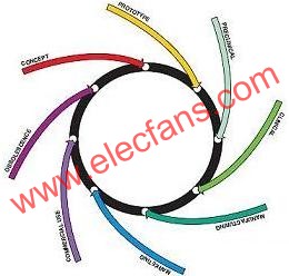
Figure 1.The entire life cycle diagram of the medical device design defined by FDA.
We can divide the entire life cycle of medical equipment into three main stages. The first is the initial stage of the entire product life cycle (Figure 2). This stage is the worst systemic stage of all three stages. During this period, the company mainly focuses on the research and development of theory and conception. The duration of this phase varies from several weeks to several years, which is closely related to the complexity of the system that the enterprise is preparing to develop.
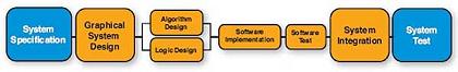
Figure 2. Applying virtual instruments and HEI design methods in the early stages of the product's entire life cycle can clearly understand the problems that need to be solved.
The basic components of the product in the early stages of the entire life cycle are data collection and analysis. Usually, researchers and product design specification teams use multiple tools to streamline the process. At this stage, HEI usually uses National Instruments (NI) LabVIEW products to adjust the FPGA I / O. Once we fully understand the problem, we can design a solution. For device development and prototyping, we combine intuitive graphical programming and reuse math and signal processing functions to develop new algorithms. Then, by using commercial hardware, we refer to real-world data to verify the performance of the algorithm. In many cases, we can use the FPGA-based prototyping platform provided by NI to implement the experimental prototype of the final device. Specifically, we can use the LabVIEWReal-TIme module and FPGA module in combination with NI CompactRIO to quickly iterate between algorithm design and device prototype stages. Prototyping with hardware kits not only significantly reduces hardware development and integration time, but also allows us to focus more on delivering powerful, reliable software designs.
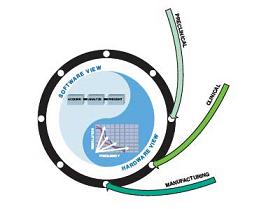
Figure 3. Software design review and verification is usually completed in the middle of the product's entire life cycle.
The second stage of the entire life cycle of a medical device can be called the mid-term of the entire life cycle of the product (see Figure 3), which can fully meet the needs of the designed device in terms of productization, verification, audit, and manufacturing. The focus of this stage is to develop a precisely defined specification document that clearly quantifies requirements. Once these specifications are defined, a clear mapping relationship can be established between the specification document and the actual implementation code.
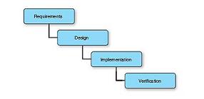
Figure 4. The traditional "waterfall" development process needs to complete each stage of development before entering the next step.
In today's intricate medical device market, customers must accelerate their time to market and get ahead first. Many companies have adopted the traditional "waterfall" development method to complete this work. Before entering the next step, the design team in the "waterfall" development method needs to complete each step of the design process (Figure 4). The waterfall method is highly dependent on having complete and accurate specifications at the beginning of the project. However, in the medical equipment market, more often the demand will continue to evolve with product development. This requires a process that can consider development and evolution. HEI's Scrum / Sprint development process is the ideal solution to fully solve this problem.
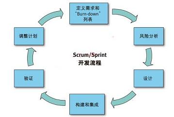
Figure 5 In the "Scrum / Sprint" process, only high-level system architecture and specifications are required to start the project.
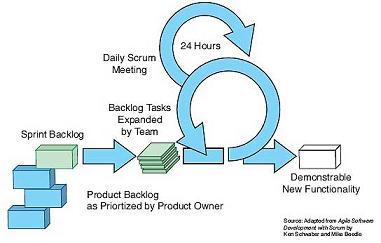
Figure 6-The project team determines the "Sprint to-do" work task for each "Sprint" in the cycle and expands and distributes it. Then, the project team evaluates the progress at the daily "Scrum" meeting and removes the related obstacles. The team delivers product features to customers at the end of each "Sprint".
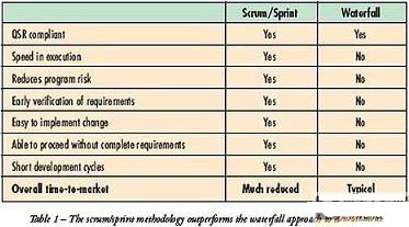
In the Scrum / Sprint process, we only require high-level system architecture and specifications to start the project. We subdivided the project into 4-6 week long "Sprint". In each "Sprint", we can identify all tasks that we think the process will require and place them in a "burn-down list". Figures 5 and 6 show related flowcharts. HEI uses the Scrum / Sprint development process company-wide, which not only speeds up our development process by 30%, but also enables us to complete the implementation of new products several months in advance. Table 1 compares the waterfall development and Scrum / Sprint development solutions.
The third and final stage of medical device development belongs to the later stage of the product's entire life cycle (Figure 7). There is very little engineering design work required at this stage, but customer feedback and market success will help promote the concept of a new generation of products, so that the life cycle has entered a new cycle.
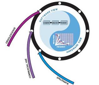
Figure 7—The later stage of the product life cycle is to bring the product to the market, obtain feedback, and help determine the function of the new generation of products. This completes the work of this cycle and brings it to a new stage of conception.
Using the Scrum / Sprint product development process, combined with FPGA-based packaged hardware and advanced FPGA software design tools from R & D to manufacturing, HEI can quickly develop derivative technologies for future products. We found that in many cases, we can use the common kernel architecture that we use in multiple product development. For example, the pump controller architecture that can adjust IV and infusion pumps can also be used in other design projects that can control motors for blood transfusion management.
Why hardware is better than software
In order to effectively use this method and further accelerate the design process, it is necessary to change the way of concept design, that is, from software-centric to more hardware-centric. As people realize, the recall of medical devices reached a new high in 2008, a 43% increase from 2007. FDA experts believe that there are two main reasons for the recall problem: there are defects in the raw materials used in production; there are problems in software development. It is relatively easy for companies to manage the quality of raw materials, but it is much more difficult to solve software quality problems. As the amount of code for device software increases rapidly, the problem will only get worse. This issue is particularly prominent after the FDA ’s Consumer Health and Safety Department stated that medical device designers have to bear many safety responsibilities.
At HEI, we think there is a potential solution to this problem, but instead of conducting more tests, code inspections, and introducing more processes, on the contrary, we are only writing as little software as possible and handing more logic to such as Hardware components such as Lingsi FPGAs are implemented. Let's take a look at the common causes of software failures and how we will use FPGAs to solve these problems.
Eliminate deadlock
Most modern devices need to be able to process multiple tasks simultaneously, while most embedded processors still have only one processing core. This means that the processor can only execute one instruction at a time. At the same time, parallel processing is not much better there, because they still have to share the main system CPU. In addition, other shared resources such as communication drives, hard disks, and user interface elements can also cause deadlocks—two or more processing processes wait for each other to release resources.
Because deadlock conditions often depend on multiple processes, and usually require events to be synchronized in sequence, deadlocks are very difficult to replicate and debug. It is difficult to find most deadlock problems just by unit testing. They are often found by code inspectors, skilled system testers, and sometimes even by luck.
In contrast, with FPGAs, independent processes have their own physical circuitry, so there are no shared resources. At the time of each clock signal, the combinational logic not only locks in each circuit, but also stores the relevant values ​​in separate registers. Since the process does not depend on other resources, the deadlock problem will not occur. This way you can trust the results of simulation and unit testing more, because unknown factors such as resource competition are no longer a problem.
Incompatible middleware
When developing embedded software, you basically do n’t need to write every line of code from scratch. There are many tools that can help firmware designers improve work efficiency, such as simple drivers, network protocol stacks, operating systems, and even code generation tools. Although these systems are usually fully and independently tested, the software will still be flawed. Due to the variety of combinations of tools and libraries, the possibility of combining components in a completely new way is very high.
For this reason, the FDA requires that for all software packages used in medical devices, companies must review the software protocol stack based on the specific use of their specific design. What does it mean? For example, if we are using a signal processing library that includes a fixed-point fast Fourier transform and need to detect the presence of specific frequency components, we do not need to verify that the FFT will return the correct value for all possible inputs. However, what we need to verify is that for all valid inputs that meet the specifications, the FFT can return the value we expect. For example, if we only detect the tones that the human ear can hear, there is no need to test whether the value returned when the input exceeds 20KHz is correct.
However, software components that appear to be independent of each other are not necessarily the case. Therefore, if we combine the software protocol stack with the SPI driver and use a real-time operating system (RTOS), we need to verify all these components to be confident in FFT. If the FFT passes the effective output to the SPI driver, but the SPI driver has a systematic failure, then the problem is obviously inevitable. Then, if we decide to adjust the SPI driver, we need to verify the entire software protocol stack again. This is very troublesome, and a faulty component will drag down the entire system development process. For this reason, at HEI, we reuse as much as possible the combination of middleware and RTOS drivers that have been tested with good characteristics. For example, we can use the middleware driver on the NI single-board RIO platform.
In addition to reviewing the software for each specific use case, we also need to review all third-party intellectual property (IP) that we use in our FPGA-based designs. However, once we have completed the verification of all of our use cases, we will be convinced: After the IP is integrated with other components, the work will be as expected. Let's take another look at the FFT example we gave above. If we use FPGAs, we can obtain or generate FFTIP cores as we do with software, and verify the correctness of their numbers according to each use case. However, the risk of intermittent failures can be greatly reduced because we do not need all the processor middleware required for software-centric design. In this way, RTOS and SPI drivers are no longer their own IP cores, because their work will not directly affect the FFT. In addition, if we adjust the implementation of the SPI driver, we do not need to review the unaffected parts of the system.
Buffer overflow management
Another example of how we use FPGAs to reduce the errors that software-centric systems usually produce is buffer overflow management. When the program tries to store data beyond the end of the memory allocated for its storage, the program repeatedly writes some adjacent data that should not be written, which causes a buffer overflow. This is a hard-to-detect defect, because the rewritten memory can be accessed at any time in the future, and this situation may cause obvious errors or may not. A common buffer overflow situation in embedded designs is caused by some kind of high-speed communication, perhaps from a network, disk, or A / D converter. If the communication interruption time is too long, the buffer will overflow, so we need to solve this problem to prevent various conflicts.
We can use FPGA to manage buffer overflow in two ways. In the first example, we use FPGA to manage cyclic transmission or double-buffered transmission, which can offload the real-time processor. In this case, the FPGA can be used as a coprocessor to reduce the interrupt load of the main processor. This is a general configuration, especially in high-speed A / D converters.
In the second example, we use the FPGA as a security layer of protection, allowing patient-specific I / O to pass through the FPGA before reaching the processor. In this case, you can add additional safety logic to the FPGA, so that when the software on the processor crashes, you can put all the outputs into a known safe state. FPGA can play the role of watchdog, its logic can ensure that the risk to the patient is minimized when the software fails. By introducing FPGA into the main signal chain of the device in the architectural design, you can use one or both of these two methods to deal with buffer overflows so that you can better deal with when a situation occurs.
In fact, the more the overall software and hardware system functions are moved to the FPGA, the sooner the design process can be completed, and the sooner we can complete the verification of our design on the customer's final product. If we can verify the reliability of our design on the overall system more quickly, then our customers can verify the entire final product more quickly and then submit it to FDA for approval. This process means that our customers can significantly accelerate the time to market of their products, improve the quality of life of patients, and even save lives.
If we use the ASIC process to implement the design, we need to produce hardware for the foundry for several months. Additional steps such as verifying the physical design of the ASIC, creating a Mask and putting the design into production will cause more chances for errors and defects. If the design fails in any of these steps, the result will be a significant delay in time to market. Since FPGAs have been produced and fully tested, we only need to care about our design and software, and ensure that the design meets customer specifications. Fully combining the "Scrum / Sprint" method, hardware-centric ideas, using highly reliable tools, and choosing FPGAs among FPGAs and ASICs, we can differentiate our customers, and thus also provide customers with customers To change.
Guangzhou TouchWo Electronics Co.,Ltd. , https://www.touchaio.com