Abstract: This paper analyzes the defects of the headlight illumination of ordinary automobiles, and designs the car auxiliary lighting follow-up system by using the single chip. The system can advance the auxiliary light source to the left front or right front of the car in advance with the steering of the car, so that the driving speed and driving safety problems are improved.
Key words: automotive auxiliary lighting; servo system; 2051 single chip microcomputer; Hall switch; stepper motor
0 INTRODUCTION Drivers driving A and B class cars will encounter such problems. When driving on a winding road or a small street in the countryside at night, they always feel that the headlights are in the same direction as the road you are driving. There is a big problem with driving speed and driving safety. The car auxiliary lighting follow-up system is based on the single chip AT892051 chip as the control core, and the stepping motor is controlled to drive the auxiliary illumination light source to rotate with the rotation of the steering wheel. It plays an auxiliary role in the headlight illumination of the car. The auxiliary lighting source adopts high-brightness LED lamp. This kind of light source has energy saving, good seismic performance and light weight. It conforms to the "auxiliary" feature and can be installed or removed at any time. Simply attach the permanent magnet at the bottom of the light source to the top of the cab or to any part of the car. The Hall switch is used to detect the steering and corner of the car and the speed of the turn. The detection signal and the reverse signal are sent to the input interface of the single-chip microcomputer. After the analysis, calculation and judgment by the single-chip microcomputer, the output signal is output from the output interface of the single-chip microcomputer. The rotation of the stepping motor and the auxiliary light source realizes follow-up control.
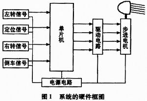
1 The basic hardware components of the system and the hardware block diagram of each part of the system are shown in Figure 1. The hardware system consists of single-chip AT89C2051 chip, 4806-A stepper motor, stepper motor drive circuit, HAM8X20PNP Hall switch, 7805 three-terminal regulator, crystal Resonator and other components.
This article refers to the address: http://
1.1 Single-chip microcomputer chip Comprehensive analysis of the control requirements of the automotive auxiliary lighting follow-up system, the selection of AT89C2051 chip circuit is simple, economical, and can fully meet the requirements. The AT89C2051 is a low voltage, high performance CMOS 8-bit controller with 2K bytes of Flash Programmable Erasable Read Only Memory (PEROM). The device is fabricated using ATMEL's high-density, non-volatile memory manufacturing technology and is compatible with the industry-standard MCS-51TM instruction set and output pins. ATMEL's AT89C2051 is a highly efficient microcontroller due to the combination of a versatile 8-bit CPU and flash memory in a single chip. In addition, it is 20 pins, 15 programmable I / O lines, 128 × 8 internal RAM, operating voltage 2.7V ~ 6V.
Set the AT89C2051 chip (P3.0, P3.1, P3.2, P3.3) as the input port, use it to collect the left turn signal, positioning signal, right turn signal and reverse signal of the system, and send it to the CPU. Analyze, compare, judge, and send the judgment result to the output port. P1.2, P1.3, P1.4, P1.5 are set as output ports, and P1. 2~P1.5 are driven by the driver to control the stepping motor to realize follow-up control.
1.2 Hall Switch The Hall switch is the main component of the sampling of the system, and the steering signal of the car is collected by it. The advantage of using a Hall switch as a sensing element is that no changes are made to the original circuit of the car. Hall switch adopts HAM8X20PNP normally open type, which has the characteristics of small size, easy installation and wide voltage range, suitable for automotive 12V power supply. The output level of the HAM8X20PNP Hall switch is easily connected directly to the microcontroller.
1.3 Stepper motor drive circuit The drive circuit adopts discrete component circuit, which consists of triode and peripheral circuits. The single-chip microcomputer outputs through P1.2, P1.3, P1.4, P1.5, and then drives the stepper motor through the triode power amplifier circuit. P1.2, P1.3, P1.4, and P1.5 are set to be active low, and the triode is selected to be 9012PNP type. This design circuit is simple and the heat dissipation performance is good.
1.4 Stepper Motor The stepper motor is the actuator of the servo system, and the 4806-A type is used. The motor has 4 phases (A, B, C, and D phases, respectively), a winding of 34 Ω, and a pulse amplitude of 12V.
1.5 Constant Current Transistor and LED Lamp The constant current transistor is the second generation semiconductor constant current device. Its biggest feature is that the constant current of the output can be adjusted by using the adjustment terminal and external components, which is most suitable for the design of LED lamps. The LED uses a 0.5W high brightness white light diode.
1.6 Power Circuit The power supply uses the car battery +12 V power supply and directly supplies the Hall switch and stepper motor drive circuit. In addition, the +12V power supply is regulated by the three-terminal regulator 7805, which becomes +5V for the microcontroller control circuit.
1.7 Clock Circuit The clock circuit consists of a 6 MHz crystal oscillator and peripheral circuits that generate a 6 MHz clock signal for the system.
1.8 Reset circuit The reset circuit is composed of the RC circuit around the 1 pin of the MCU. When the MCU control circuit is powered on, a positive pulse is generated at the RST terminal to start the MCU operation.
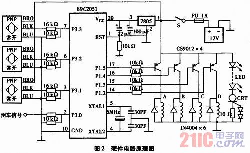
The hardware circuit schematic is shown in Figure 2:
2 software flow chart Software flow chart shown in Figure 3. According to the system function requirements, when the switch S is closed, the system starts, and the single-chip microcomputer detects the left, middle and right three Hall switches, and the auxiliary illumination source is turned on, and the light is bright. When the direction is left, the MCU controls the stepper motor to turn left. When the direction is turned to the right, the MCU controls the stepper motor to turn right. When the direction is positive, the MCU controls the stepper motor to go to the middle position.
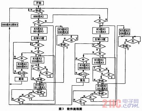
But in fact, there may be three situations when the direction is left-turned: one is to turn left half a turn and one left turn signal is detected; the other is to turn left one turn, and measure a left turn signal, a right turn signal and an intermediate signal; It is a left turn and a half turn, measuring a left turn signal, a right turn signal, an intermediate signal and a left turn signal. Any of these three conditions causes the stepper motor to turn left 30 degrees. In the same way, there are three cases when turning right: one is to turn right half a turn, and one right turn signal is detected; the other is to turn right one turn, and measure a right turn signal, a left turn signal and an intermediate signal; One turn and a half, a right turn signal, a left turn signal, an intermediate signal and a right turn signal are detected. Either of these three conditions is to turn the stepper motor to the right by 30 degrees. Therefore, we control the left and right turn of the stepper motor and can not directly control the left and right turn of the stepper motor according to the detected left and right state signals, but the analysis and judgment according to the above six conditions, complete the stepper motor The left and right rotation controls are used to solve the problem of lighting in the left and right directions of rotation during night driving.
3 Conclusion The above is the design of the hardware part of the car auxiliary lighting follower system, interface distribution and software flow. In the future, it is necessary to design the shape of the LED luminaire from the aerodynamic point of view, design the rotating part of the auxiliary lighting system from the perspective of waterproof sealing, adjust and optimize the control program, and strive to be simple, applicable, reliable and economical. .
The biggest features of Front Service Led Display is is to save space! For the indoor or mosaic installation structure, the empty space is very small that not convenient for the maintenance. The outdoor front service Led Display is mainly use for front open cabinet, which can greatly reduce the overall thickness of the led display structure, and can not only be well integrated with the surroundings, but also can save the space while ensure the effect.

Front Service Led Display
Front Service Led Display,Led Wall Panel,Led Scrolling Text Display,Led Indoor Display
Shenzhen Cxcolor Optoelectronics Co., LTD. , http://www.largeledscreen.com