introduction
This article refers to the address: http://
Large-scale programmable logic devices CPLD and FPGA are the two most widely used programmable logic devices in today. Electronic design engineers can use it to design their own dedicated chips and special products in the office or laboratory, thus greatly shortening the product. Time to market reduces development costs. In addition, programmable logic devices have the characteristics of static reprogrammability and dynamic system reconfiguration, so that hardware functions can be modified by programming like software, which greatly improves the flexibility and versatility of electronic system design. .
1 Working principle
MIDI music is a kind of synthetic music under Windows. Because it records a piece of music by means of notation, it can greatly reduce the storage capacity compared with wave music. The basic principle of MIDI music: the frequency value (tone) of each note that makes up the music and its duration (sound length) are the two basic data that the music can play continuously, so as long as the frequency of the excitation signal output to the speaker is controlled. The high and low levels and the duration of each frequency signal allow the speaker to emit continuous music.
FIG. 1 is a schematic block diagram of a music player designed in this paper. The music encoder stores the codes of the four preset songs, and by changing the state of the music selection switch, it is possible to determine which music is currently to be played. The music encoder controls the tone generator and the flashing controller of the lantern. When the music rhythm clock is sent to the music encoder for one clock pulse, the music encoder sends the code of the note to be played to the tone generator and the lantern. Flash controller. The tone generator divides the 2MHz reference clock according to the frequency division coefficient corresponding to the code to obtain the pulse of the frequency corresponding to the note to be played, and then uses the pulse to excite the speaker to obtain the sound of the note. The flashing controller sends the lantern corresponding to the currently playing note to the lantern according to the encoding.
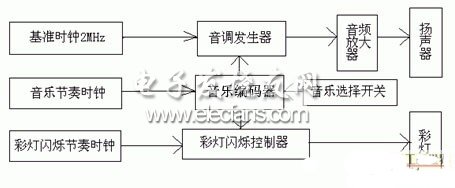
Among them, the three functions of tone generator, music encoder and lantern controller can be completed by ALTERA company programmable logic device (CPLD) EPF10LC84-4 chip in VHDL language [1-3]. Audio amplifiers, lanterns, and various clocks can be implemented by specific peripheral circuits.
2. MIDI music generator chip design
The key to this design is to accurately generate the frequency signal corresponding to each note in the music, and output it according to the tune requirements. In order to reduce the complexity of the system, the design according to the principle of the variable modulus counter, according to the music required to change the preset number of the counter, can generate the frequency signal required by the music. The block diagram of the chip is shown in Figure 2. The chip is designed in the MUXPLUS II environment using the VHDL hardware description language.
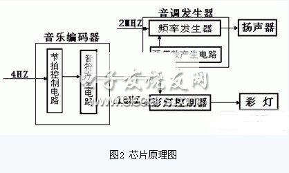
The beat control circuit generates a beat timing signal; the note generating circuit generates the notes required for the music according to the beat request; the preset value generating circuit is controlled by the note, generates a preset number corresponding to the note frequency, and inputs the data input of the counter. end. The note frequency generator generates a corresponding frequency signal according to different preset numbers, thereby completing the performance function of the music piece.
3 peripheral circuit design
3.1 music rhythm clock and lantern flashing rhythm clock generation circuit
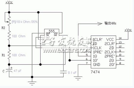
The music rhythm clock we need is a 4 Hz clock pulse, the frequency is very low, can be generated by the multi-vibrator composed of 555 timer, as shown in Figure 3.
The 555 integrated timer is a hybrid integrated circuit that combines analog functions and logic functions. The multi-harmonic oscillator circuit diagram of the 555 timer is shown in Figure 3. The calculation formula of the pulse frequency output by the 3-pin is:
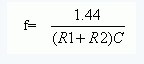
Changing the resistance of the variable resistor changes the output frequency. We require the output frequency to be 4Hz, C=47Uf, so R1+R2 should be 7.66K.
The music rhythm clock is very important for the whole music player. It requires the music rhythm clock pulse to be very stable, so that the music can be played smoothly. Otherwise, the sound will be a messy sound, not music but noise. In order to make the output pulse relatively stable and reduce external interference, the output pulse is sent to the CPLD chip through the D flip-flop (7474), so the pulse frequency output by the 555 timer device should be doubled (ie 8Hz), so R1 The resistance of +R2 should be 3.83K.
The flashing rhythm clock generation circuit has the same principle as the music rhythm clock generation circuit, and is also realized by a multi-vibrator composed of 555 timers, except that the frequency of the lantern control clock generation circuit is higher than the frequency of the music rhythm clock generation circuit. Between ten and a few tens of hertz, its R2 value is not fixed, can be determined according to their own requirements, if you want the flashing light to flash faster, the frequency is higher, and the slower flashing frequency is lower. 3.2 audio power amplifier circuit
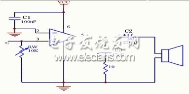
The audio signal output by the CPLD chip is very weak and cannot directly drive the speaker. Therefore, an audio amplifier circuit is required to amplify the output audio signal and then drive the speaker. We use an audio power amplifier consisting of an integrated power amplifier, the LM386, as shown in Figure 4. Among them, C2 is an AC coupling capacitor, which sends the AC output of the power amplifier to the load, and the output signal is connected to the non-inverting terminal of the LM386 through Rw. C1 is a decoupling capacitor, and the R1-C3 network acts to eliminate high frequency self-oscillation.
3.3 music selection switch and lantern flashing control circuit
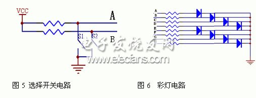
The two parts of the circuit are very simple. In the music selection switch circuit (Fig. 5), the A terminal is high when S1 is open, the A terminal is low when closed, and the B terminal is high when S2 is open. The B terminal is at a low level, and the states of A and B are changed by the opening and closing of S1 and S2, thereby realizing the selection of four music.
The flashing control circuit (Fig. 6) is composed of light-emitting diodes. The high and low levels of the eight-terminal levels of A, B, C, D, E, F, G, and H control the lighting of the eight LEDs.
4 system debugging
Connect the above parts of the circuit to a pre-designed MIDI music generator chip (EPF10LC84-4) to form the entire system.
The system debugging mainly debugs the music rhythm clock, the frequency of the lantern control clock and the audio power amplifier circuit.
1. Tuning of the music rhythm clock: The music rhythm clock theory requires 4 Hz. In the actual performance process, the frequency is slightly higher than 4 Hz. The effect is changed by changing the resistance of R1 to change the rhythm of the music. Table 1 is a record of the music rhythm clock debugging process.
Table 1 Music rhythm clock debugging record
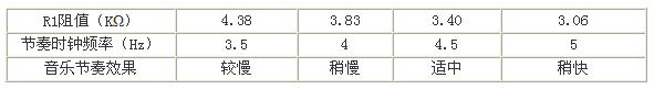
After comparison, the resistance of R1 is finally set at 3.4 KΩ, and the frequency of the music rhythm clock is 4.5 Hz.
2. Commissioning of the lantern control clock: The color control clock frequency is required to be between ten and several tens of hertz. Table 2 is a record of the lantern control clock debugging process.
2. Commissioning of the lantern control clock: The color control clock frequency is required to be between ten and several tens of hertz.
Table 2 Lantern control clock debugging record
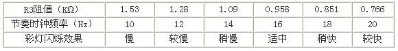
After comparison, the resistance of R1 is finally set at 0.958 KΩ, and the frequency of the control clock of the lantern is 16 Hz.
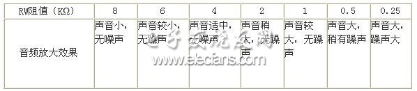
3. Debugging of audio power amplification: The voltage value of the audio signal input to the audio amplifier LM386 is changed by adjusting the resistance of RW. The debugging results are shown in Table 3.
Table 3 Audio amplification debug record
All our outdoor lighting equipments are IP65 rated to test its ability to withstand the harsh outdoor life. Whether it's a large parking lot or an ordinary courtyard, LEDER has the right outdoor lighting. Suitable for outdoor places such as driveways,paths and parking lots.
l IP65 outdoor rated
l Corrosion resistant finish
l 3 year warranty
Outdoor Lighting
Outdoor Hanging Lights,Outdoor Patio Lights,Outdoor Post Lights,Outdoor Flood Lights
JIANGMEN LEDER LIGHTING CO., LTD , https://www.lederlight.com