An electric car is a car that is driven, in whole or in part, by a motor. At present, there are three types of pure electric vehicles, hybrid electric vehicles and fuel cell vehicles. The current power used in electric vehicles comes from lead-acid batteries, lithium batteries, and nickel-metal hydride batteries.
This article refers to the address: http://
Lithium batteries have high cell voltage, high specific energy and high energy density, and are currently the most energy-efficient batteries. However, it is precisely because the lithium battery has a relatively high energy density, which may cause a safety accident when misuse or abuse occurs. The battery management system can solve this problem. When the battery is under charging overvoltage or discharge undervoltage, the management system can automatically cut off the charge and discharge circuit, and its power balance function can ensure that the pressure difference of the single cell is maintained within a small range. In addition, it also has functions such as over temperature, over current, and residual power estimation. This paper is designed as a battery management system based on single chip microcomputer [1].
1 battery management system hardware components
For the hardware circuit of the system, it can be divided into MCU module, detection module and equalization module.
1.1 MCU module
The MCU is the core of system control. The MCU used in this paper is the MZHC08 series GZ16 model MCU. All MCUs in the series feature the enhanced M68HC08 central processor (CP08). The microcontroller has the following features:
(1) 8 MHz internal bus frequency; (2) 16 KB internal FLASH memory; (3) 2 16-bit timer interface modules; (4) Clock generators supporting 1 MHz to 8 MHz crystal oscillators; (5) Enhanced Type Serial Communication Interface (ESCI) module.
1.2 Detection module
The voltage detection, current detection, and temperature detection modules are described separately in the detection module.
1.2.1 Voltage detection module
In this system, the single chip will detect the overall voltage and single voltage of the battery pack. There are two methods for detecting the overall voltage of the battery pack: (1) using a dedicated voltage detection module, such as a Hall voltage sensor; (2) constructing a resistor divider circuit using a precision resistor. The use of a dedicated voltage detection module is costly and requires a specific power supply, and the process is complicated. Therefore, a voltage-divided circuit is used for detection. The voltage variation of the 10-string lithium manganate battery pack ranges from 28 V to 42 V. Using 3.9 M? 赘 and 300 k? 赘 resistors for voltage division, the voltage signal collected varies from 2 V to 3 V, and the corresponding AD conversion results are 409 and *.
For the detection of single cells, the fly capacitor technology is mainly used. The schematic diagram of the flying capacitor technology is shown in Figure 1 [2], which is the protection circuit diagram of the 4 sections of the battery pack. The voltage of any 1 battery of the last 4 batteries can be collected into the MCU through the four-channel switch array. The driving signal is output to control the turning on and off of the MOS tube, thereby protecting the charging and discharging of the battery pack.
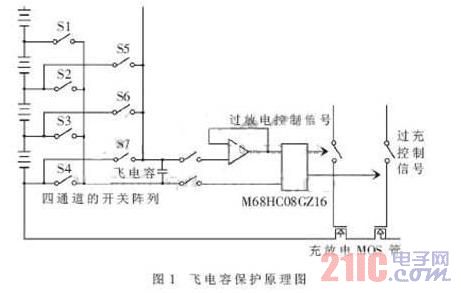
As shown in Figure 1, for the protection circuit diagram of the 4th section of the battery pack, the voltage of any 1 battery of the last 4 batteries can be collected into the single-chip microcomputer through the four-channel switch array, and the single-chip microcomputer outputs the driving signal to control the guide of the MOS tube. Turns on and off to protect the battery pack from charging and discharging.
The above six batteries can be realized with two three-channel switch switching arrays. The MAX309 is a 4-to-1, dual-channel multiplexer that selects the channel by location. Switches S5, S6, S7 are responsible for connecting the positive terminal of the battery to the positive terminal of the flying capacitor. Switches S2, S3, and S4 are responsible for connecting the negative terminal of the battery to the negative terminal of the flying capacitor. The three-channel switch-switching array structure is similar to the four-channel switch-switching array except that the number of channels is one less. When working, the MCU sends the channel selection signal, so that the positive and negative terminals of one of the batteries are connected with the capacitor, the capacitor is charged, then the channel switch is turned off, the switch of the following amplifier is turned on, and the single-chip microcomputer quickly detects the voltage of the capacitor. This completes the voltage detection of one battery. If the detection voltage is found to be less than 2.8 V, it can be inferred that the battery may be short-circuited, over-discharged, or the detection line of the protection system to the battery is disconnected, and the MCU will immediately send a signal to cut off the main loop MOS tube. Repeat the above process, the microcontroller will complete the detection of the battery managed by this module.
1.2.2 Current Sampling Circuit
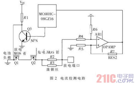
The parameters in the battery management system are an important basis for battery overcurrent protection during current sampling. The current sampling circuit in this system is shown in Figure 2. When the battery is discharged, the current signal is detected by the constantan wire, and the detected voltage signal is amplified by the differential mode amplifier, and the voltage signal of 0 to 5 V is sent to the single chip microcomputer. If the current of the discharge is too large, the voltage signal detected by the single-chip microcomputer is relatively large, it will drive the triode action, change the gate voltage of the MOS transistor, and turn off the discharge circuit. For example, for a 36 V lithium manganese oxide battery, the protection current is set to 60 A. The resistance of the constantan wire is about 5 mΩ. When the current reaches 60 A, the voltage of the constantan wire reaches about 300 mV. In order to improve the accuracy, the voltage is amplified by the amplifier 10 times and sent to the MCU for detection.
1.2.3 Temperature detection
During the charging and discharging process of the battery pack, part of the energy is released in the form of heat. If this part of the heat is not removed in time, the battery pack may be overheated. If the temperature of a single NiMH battery exceeds 55 °C, the battery characteristics will deteriorate, and the battery pack charge and discharge balance will be broken, which will cause permanent damage or explosion of the battery pack. In order to prevent the above situation, the battery pack temperature needs to be monitored in real time and heat-dissipated.
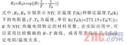
A thermistor is used as a temperature sensor for temperature sampling. The thermistor is a heat-sensitive semiconductor resistor whose resistance decreases as the temperature increases. The resistance temperature characteristic can be approximated by the following formula:
1.3 Equilibrium Module
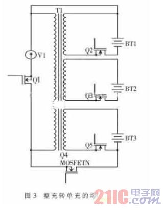
Commonly used equalization methods for battery packs include shunting method, flying capacitor equalization charging method, and inductive energy transfer method. In this system, more I/O ports are needed to drive the switch tube, and the I/O port of the single chip microcomputer is limited, so the charging equalization method of the full charge to the single charge is adopted. The schematic is shown in Figure 3. Q4 is a switch that controls the charging of the battery pack. Q2, Q3, and Q5 are switches that control the charging of a single battery. Taking a 10-cell lithium manganate battery pack as an example, the voltage across the main coil of the transformer is 42 V, and the voltage of the secondary coil is 4.2 V of the rated voltage of the battery. At the beginning of Q4 conduction, Q2, Q3, Q5 cut off, the voltage of a single battery is continuously rising. When the voltage of a certain battery reaches the rated voltage of 4.2 V, the voltage detection chip sends a driving signal, closes Q4, and opens Q2. Q3, Q5, the whole system enters the single charging phase, and the unfilled battery continues to be charged, so that the battery with the rated voltage maintains the rated voltage. After testing, the voltage difference does not exceed 50 mV.
2 SOC power detection
In the lithium-ion battery management system, the commonly used SOC calculation methods are open circuit voltage method, Coulomb calculation method, impedance measurement method, and comprehensive table look-up method [3].
(1) The open circuit voltage method is the simplest measurement method, and the size of the SOC is mainly determined according to the magnitude of the open circuit voltage of the battery. It can be known from the operating characteristics of the battery that there is a certain correspondence between the open circuit voltage of the battery and the remaining capacity of the battery.
(2) Coulomb calculation method is to measure the charge and discharge current of the battery, integrate the product of the current value and the time value, and calculate the amount of charge and the amount of electricity discharged, and estimate the value of SOC.
(3) The impedance measurement method uses a linear relationship between the internal resistance of the battery and the state of charge SOC, and calculates the internal resistance of the battery by measuring the voltage and current parameters of the battery, thereby obtaining an estimated value of the SOC.
(4) The remaining capacity SOC of the battery in the comprehensive look-up table method is closely related to the parameters such as voltage, current and temperature of the battery. By setting a correlation table and inputting voltage, current, temperature and other parameters, you can query the remaining capacity value of the battery.
In this design, the software programming method is adopted from the aspects of circuit integration, cost, and performance of the selected MCU. Combining several methods, it is more appropriate to use the Coulomb calculation method.
(1) Use C to indicate the total amount of electricity discharged from the lithium battery pack from 42 V to 32 V.
(2) Use η to represent the ratio of the amount of electricity discharged to the current after the e-time e has elapsed.
The CRM is the remaining power. Let ΔCi=i×Δt denote the discharge amount of the battery pack discharged by i in the t-time; or the charge amount charged by i, the remaining power is actually the calculation and accumulation of ΔCi. Set the appropriate sampling time Δt, measure the current current value, and then calculate the product to obtain the amount of change in the remaining capacity CRM in Δt, so as to continuously update the value of CRM, the SOC power can be detected.
3 test results
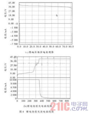
The lithium manganese oxide battery pack was tested for charge and discharge by a battery management system. Figure 4(a) shows the discharge test of the lithium battery pack with a discharge current of 8 A. When the battery pack voltage drops to 32 V, the discharge MOS transistor is turned off. Figure 4(b) is a test chart for charging. After 4 hours of charging, the equalization is completed.
The battery management system of this paper takes M68HC08GZ16 as the core, and realizes the collection of voltage, current and temperature signals of the battery unit. After the charge balance, the voltage difference between the cells does not exceed 50 mV. The overall system has good running performance and can meet the needs of electric vehicle battery pack applications.
Rental LED Video Display screens
LED display screen Video walls are extensively used for a wide range of applications such as rental, event and information sharing, advertising, and as an entertainment medium. They perfectly complement the advances in digital marketing techniques. They are being used for internal communications at indoor locations and for publicity and advertising purposes at outdoor locations.
Owing to the decades of industry experience,Priva Led has successfully developed LED Display Screen Video Wall solutions with a wide range of different applications, resolutions, and sizes. Many other LED displays in broad daylight give an unclear picture quality and dull display. Where most of the LED display manufacturers fail to deliver; Priva Led`s highly experienced Led display video wall experts have made sure that even under direct sunlight, our LED screens have the clearest and the brightest displays.
LED display video walls are sector agnostic product but customization is always required as per industry served. The shapes and sizes of LED walls, applications required and budgets of clients varies according to the respective business needs of particular sector. Equipped with the most flexible mounting systems, our LED Video walls have no limitation in shape or size or installation platforms. Also, our LED Screens can be monitored from a remote location and these LED display screen walls are effective in tough outdoor environments such as high temperatures, direct sunlight.
For more information on our LED Screen Video Walls, please browse through our website
Outdoor Rental LED Display -RO Series
Rental Led Display,Outdoor Rental Led Display,Ro Series Outdoor Rental Led Display
Shenzhen Priva Tech Co., Ltd. , https://www.privaled.com