1 Introduction
Modern mobile communication devices are increasingly focusing on mobile device power issues. The core problem of mobile power is the management problem of rechargeable batteries. Since the management of batteries is closely related to the chemical characteristics of batteries, different types of batteries have different charging and use characteristics. Even if the same type of batteries have different characteristics of battery materials, Charging and use requirements are also different, so it is an urgent requirement for battery users to make the battery itself intelligently managed. In order to solve the problem of battery use, the "plug and play" of the battery is realized, and the smart battery is widely used. Some well-known battery companies in the world have developed a smart battery system for their own battery characteristics.
At present, there are two ways to realize intelligent battery, one is realized by some special integrated circuits, and the other is realized by a single-chip microcomputer integrated with analog modules. The ASIC solution has the following disadvantages: the electrical interface and the standard are not uniform for the characteristics of one type of battery and one type of battery, and some ASICs cannot keep up with the development of battery technology. This paper adopts the single-chip microcomputer scheme to realize the intelligent management of 18650 battery produced by lithium-cobalt material system, and consider the development of battery technology in the future, and draws on the mature application of smart battery technology, and selects SMBus1.1 as smart battery data. Communication interface, the program has the characteristics of universal, scalable, and easy to upgrade.
2 system composition and its main functions
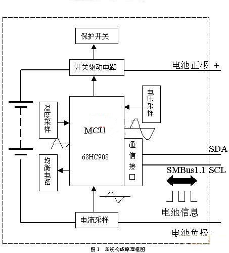
The block diagram of the system structure is shown in Figure 1.
This system uses Motorola68HC908 single-chip microprocessor (referred to as MCU) to manage the four series of 18650 lithium-ion batteries in series. The MCU has a 12K flash memory that can be erased 100,000 times online. It has 14 channels of A/D 10 bit signal acquisition port, two gain programmable operational amplifiers, SMBus1.1 interface and low power operation mode, which can easily realize multi-channel analog signal acquisition and data implementation according to SMBus1.1 protocol. Communication function, in addition, the series of MCUs have perfect electromagnetic compatibility protection measures, strong anti-interference ability and high reliability. They can be widely applied to power electronics, automobile control, and military fields, and can realize nickel-hydrogen batteries. The intelligent control of cadmium-nickel batteries and lithium-ion batteries meets the design and use requirements of intelligent batteries. In this solution, the smart battery mainly has the following functions by interconnecting the MCU and the battery pack:
Power supply function
When the smart battery is docked with the appliance, the MCU will automatically wake up to control the battery to supply power to the appliance. In addition, it can also be used together with intelligent chargers and hand-cranked generators to supply power to the device.
Charging function
Smart batteries are charged via smart chargers, which exchange information via the SMBus bus interconnect. Lithium-ion battery charging generally takes two stages. First, constant current charging is performed. When the battery voltage reaches a certain value, it is changed to constant voltage charging. Therefore, the MCU should constantly monitor the battery pack voltage to control the charging voltage.
Communication function
The battery and the electric appliance and the intelligent charger can mutually transmit the fixed information, the dynamic information and the alarm information required by each other. The fixed information includes: battery manufacturer information (manufacturer, production date, production batch number), battery chemical composition, rated voltage, rated capacity, specification information, name and other information. Dynamic information includes: remaining capacity, full charge capacity, battery mode, temperature, temperature rise, charging voltage, charging current, number of cycles, remaining working time, battery status (alarm) and other information.
In addition, the smart battery also has the functions of remaining capacity LED display and automatic protection.
3 system hardware circuit design
3.1 Signal acquisition
In this system, the signals collected by the MCU include voltage signals, current signals, and temperature signals. The method of collection is as follows:
Voltage measurement
The voltage is measured by a resistor divider sampling voltage. The voltage at the battery pack is measured by measuring the voltage value of the voltage divider resistor. The resistor divider ratio is 1:7, and the resistor accuracy is ±0.5%. The voltage value sampling of the divided piezoelectric group is completed by the internal 10Bit ADC of the MCU.
Current measurement
The current is measured using a precision current sampling resistor to measure the current. A 20 mΩ precision resistor was placed in series with the negative pole of the battery pack. The operating current was measured by measuring the voltage drop of this resistor with a resistance accuracy of 0.5%. The measurement of the voltage across the precision resistor is also done by sampling the ADC built into the MCU.
Temperature measurement
The temperature is measured by a thermistor with a negative temperature coefficient. The temperature of the thermistor is measured by measuring the resistance of the thermistor. The thermistor resistance is 1%. The thermistor should be placed close to the surface of the battery, and each of the two batteries share a thermistor.
3.2 Balance protection circuit design
The voltage of each battery should be monitored during charging and discharging of lithium-ion batteries. Because the voltage rise and fall of the four cells connected in series in the same current charging and discharging may not be the same, which will cause overshoot or overdischarge of a certain battery, so increase the battery equalization circuit and make the battery voltage of 4 series connected in series. Keep the time consistent within a certain error range. In this solution, the I/O port of the MCU is used to control the operational amplifier, so that the battery with a faster voltage change is temporarily charged and discharged through the triode.
3.3 protection switch design
The protection switch selects the power MOS tube as the charge and discharge protection switch, and the MOS tube is selected as the IRF4905. The IRF4905S has an on-resistance of 5 milliohms and a current of 60 A. The turn-on and turn-off of the MOS transistor is controlled by the I/O port of the MCU. Since the power of the I/O port is limited, a triode driving circuit is added to the I/O port and the MOS tube in the system.
3.4 system low power design
For devices that require continuous power supply, devices with lower leakage current should be selected. The regulated power supply selects the TPS71533, and the op amp selects a low-power op amp. The measuring circuit is designed with switches that are turned on and off. The sampling circuit is turned off in the state where no measurement is required to reduce the loss of power. A low power control strategy is selected for control. When the smart battery is charging, supplying power to the appliance, and displaying the button press, the MCU works in the Run mode and the Wait mode, and the rest of the time works in the STOP mode. When the MCU works in the STOP mode, the voltage measurement and temperature measurement circuit must be turned off. To reduce battery power consumption. Entering Run mode from Stop mode requires external conditions to wake up. The wake-up mode adopts the method of displaying the button wake-up mode and current wake-up. When the display button is pressed, the CPU enters the Run mode from the Stop mode; when a current flows through the sampling resistor, the CPU enters the Run mode from the Stop mode. In Run mode, no events occur within 10 minutes and the MCU automatically enters Stop mode.
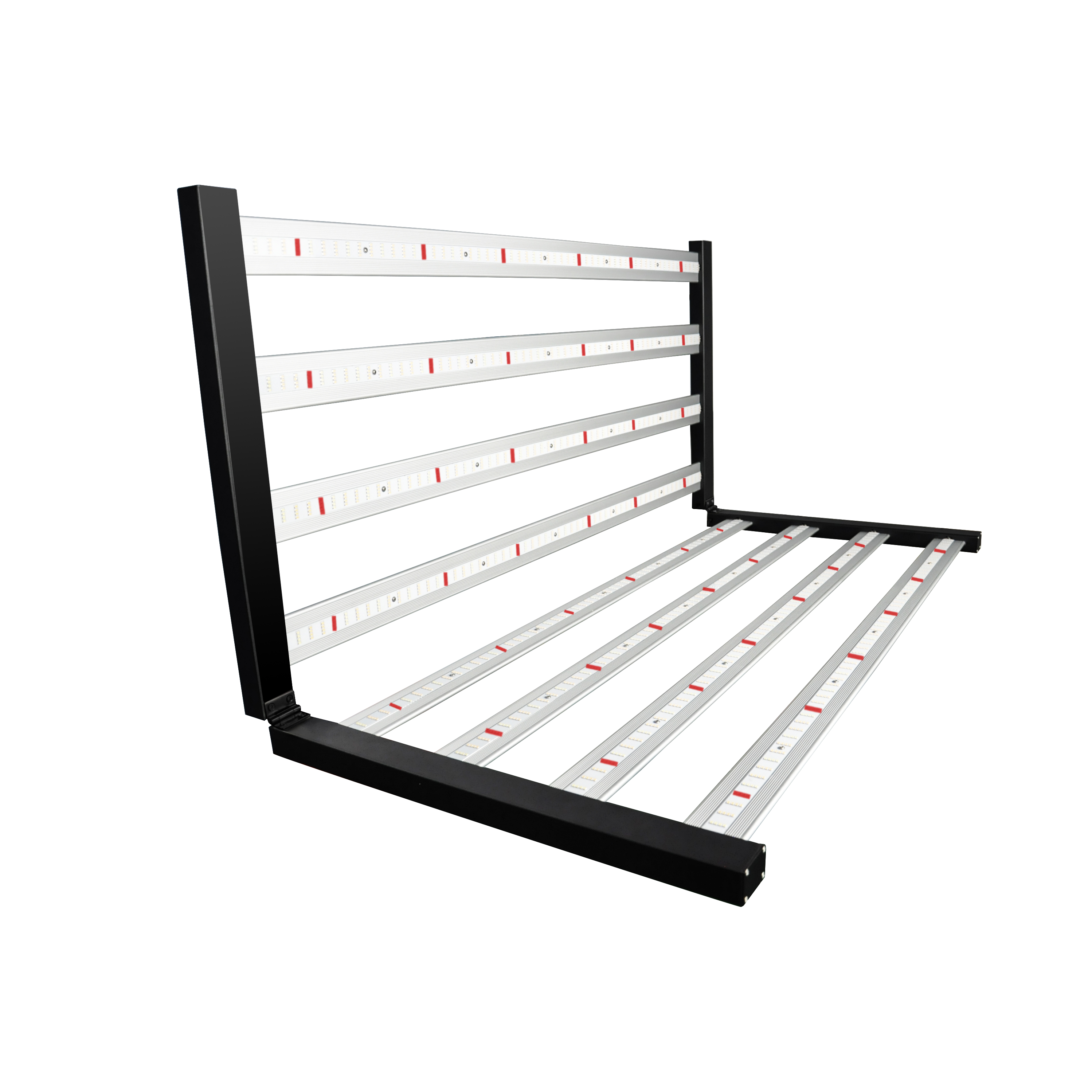
Grow Light Spider series has 4pcs to 10pcs led strips lights which consist of the whole grow light, the light can be 180 degree folding, it has higher efficiency and more energy saving compare to t5 grow lights.
ZY Grow Light is one of the best solutions for various farming systems.
Our plant growth lamp is a full spectrum lamp, which can meet the growth needs of plants throughout their life cycle from seed stage, germination, flowering to fruiting. One product meets all the needs of agricultural investors.
bar series led grow light mainly divides into two kinds: folding grow lights and non-folding grow lights.
You can differ each other from the pictures directly.
Both two kinds have from 4 strips to 10 strips even 12 or more stripss if customer need.Our products can be customized to match special or different requirements.

Grow Light Spider
spider farmer led, spider plant light, spider led grow light
Shenzhen Zhenyang Century Technology Ltd. , https://www.growlightzy.com