Abstract: The main functions and features of CAN bus, CAN controller and CAN bus in hybrid motor vehicle control system; CAN bus and motor control chip TMS320F241 interface design, frame structure and communication interrupt service program flow chart.
This article refers to the address: http://
Keywords: CAN bus hybrid electric vehicle motor control system
CAN (Controller Area Network) bus is the controller area network, which is a serial communication network that effectively supports distributed control or real-time control. It belongs to the field bus field. Bosch in Germany successfully researched it in the early 1980s, initially for data communication in automotive interior inspection and control systems. The CAN bus communication protocol was developed in the context of fully considering the industrial site environment. It uses three layers in the Open Systems Interconnection (ISO-OSI) model developed by the International Organization for Standardization (ISO), namely the physical layer, the data layer and the application layer. Is a simplified network structure of OSI. The CAN bus specification has been developed by the International Organization for Standardization as the international standard ISO11898, and has been supported by famous semiconductor device manufacturers such as Motorola, Intel, Philips, etc., and has rapidly introduced various products integrated with the CAN protocol. At present, the CAN bus is mainly used in the field of automotive automation, such as automatic ignition, oil injection, complex acceleration brake control, anti-lock brake system and anti-slip system applied to the engine. With the increasing emphasis on environmental protection, research on Hybrid Electrical Vehicles (HEVs) and Electric Vehicles (EVs) is developing rapidly. Since both types of vehicles use motor drive systems, motor control systems Communication with the CAN bus is an important issue. This paper mainly discusses the application of CAN bus in motor control system.
1 CAN bus features and features
(1) The data block-oriented communication method is adopted, and the signal transmission uses a short frame structure, and the data amount per frame is 8 bytes. If the communication distance is within 40m, the data transmission rate can reach 1Mbps.
(2) It can realize multi-master working mode and flexible data transmission and reception. It can realize several transmission methods such as point-to-point, point-to-multipoint, and global broadcast.
(3) The CAN bus adopts a non-destructive bus arbitration method based on priority competition.
(4) CAN has CRC check and other inspection measures, and has error recognition and automatic retransmission function.
(5) The communication medium can be twisted pair, coaxial cable or optical fiber.
(6) The interface is simple, the programming is convenient, and it is easy to form a user system.
In short, CAN bus has the advantages of strong real-time performance, high reliability, strong anti-interference ability, simple structure, good operability and low price. It is recognized as one of the most promising fieldbuses.
2 CAN controller
The TMS320F241 is one of TI's TMS320 series of fixed-point digital signal processors. It is designed for digital motor control. Its instruction execution speed is 20MIPS. Almost all instructions can be executed in a single 50ns cycle. At the same time, the TMS320F241 chip has a CAN module embedded in it, so this chip is the preferred chip for designing a digital motor control system based on CAN bus. The CAN module of the TMS320F241 is a FullCAN controller, including a message processor (responsible for receiving and transmitting management and frame storage), which requires less CPU overhead than the BasicCAN controller and adapts to the technical specification CAN2.0B, so it can send and receive standard frames. (11-bit identifier) ​​and extended frame (29-bit identifier). At the same time, the CAN mode consists of six mailboxes (Mailbox) and 15 different 16-bit registers, which are the control register, status register, interrupt register and receive mask register.
3 CAN bus application in HEV motor control system
3.1 Hardware Design
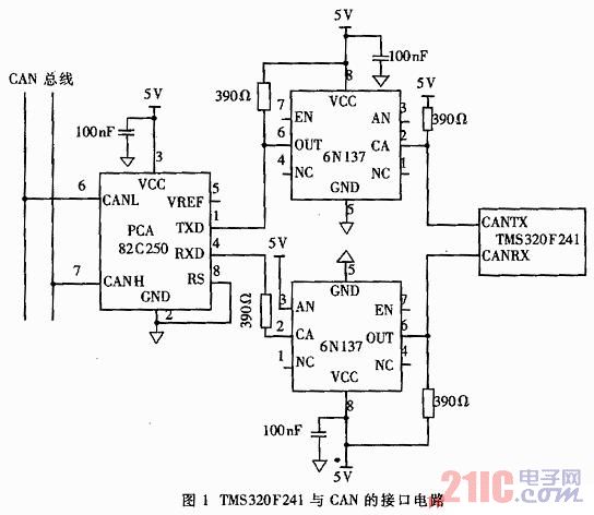
The bus transceiver of the TMS320F241 chip and CAN bus interface uses the PCA82C250 chip of Philips. The 82C250 provides differential transmit capability to the CAN bus and differential receive capability to the CAN controller. The communication medium uses twisted pair, and the maximum communication rate of differential transmission and differential reception is up to 1 Mbps. In order to enhance the anti-interference ability, high-speed optocoupler 6N137 is used for isolation between TMS320F241 and 82C250.
The interface circuit of TMS320F241 and CAN bus is shown as in Fig. 1.
3.2 Frame structure
The message transmission between the motor control unit (MCU) and the vehicle control unit (VCU) is represented and controlled by two types of frames: the data frame carries data from the transmitter to the receiver; the remote frame is sent through the bus unit to request Send a data frame with the same identifier. The data frame and the remote frame are separated from the current frame by the frame space.
3.2.1 Data frame
There are two different frame formats in CAN Technical Specification 2.0B, the main difference being the length of the identifier, the frame with the 11-bit identifier is called the standard frame, and the frame with the 29-bit identifier is called the extended frame. The data frames in this system use standard posts. The data frame consists of 7 different bit segments, including frame start (SOF), arbitration segment, control segment, data segment, cyclic redundancy check segment (CRC), response segment (ACK), and end of frame (EOF). The arbitration segment is composed of an identifier and a remote transmission request bit (RTR); the control segment is composed of a data length code (DLC) and two reserved bits r0, r1; the data segment is composed of data transmitted in the data frame, which includes 0. ~8 bytes, 8 bits per byte.
The data frame sent by the VCU to the MCU includes: MCU initialization, detection of MCU, VCU unrecoverable error, VCU operating state, control of motor speed, control of motor torque, request to return to the motor's error status, etc.
The data frame sent by the MCU to the VCU includes: returning the current state of the MCU, sending back the motor speed, returning the motor torque, motor or MCU error, and the motor is working normally.
In order to distinguish between different requests and commands issued by the VCU, the Universal Serial No byte is used. This byte is located in the first byte of the data segment and represents the request or command and number.
3.2.2 Remote frame
The remote frame has the same structure as the data frame except that it does not include the data segment. The remote request send bit of the remote frame is 1. Remote frames are used to request information. The CAN module of the TMS320F241 can automatically reply to the remote signature, that is, the node receives the remote frame. If there is a message in the node with the same identifier as the remote frame, the node sends the corresponding data frame to the bus. In this system, the remote frame is the same as the data frame, and the standard format is adopted.
The remote frame sent by the VCU's MCU includes: request to return to the motor state, request to return the motor speed, request to return the motor torque, and so on.
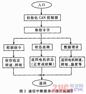
3.3 Communication Interrupt Service Program
After the VCU instruction reaches the MCU through the CAN unit, the MCU is transferred to the communication interrupt service subroutine in the form of an interrupt (such as IRQ5). In order to ensure that the VCU's instructions can be sent to the MCU in time. The communication interrupt service subroutine flow chart is shown in Figure 2.
Single Burner Electric Hotplate
Portable Hot Plate,Single Burner Electric Hotplate,Hot Plates,Hot Plates With Stainless Housing
Shaoxing Haoda Electrical Appliance Co.,Ltd , http://www.zjhaoda.com